

Quality of impeller parts, both in production and inspection, is directly related to the reliability and stability of the overall machine operation. In the last few years, with the acceleration of manufacturing technology in aviation, energy, and precision fluid equipment, impeller structures have increasingly become complex and miniaturized. The design of light enables extreme thinning of wall thickness, lowering wall thickness in some key components to below 0.5mm, which imposes extremely stringent standards in the production and measurement process.
Introduction
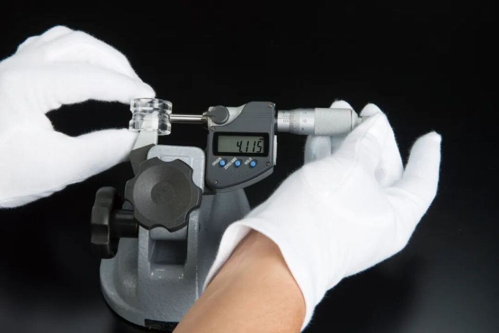
When I actually worked on impeller production projects, I deeply realized that traditional measuring devices (e.g., vernier calipers and micrometers) show problems such as poor precision, high dependence on operation, and traceability-less data in the measurement of impeller parts having complex surfaces and tight structures. Conversely, high-accuracy digital measuring instruments greatly enhanced the stability and efficiency of measurement through the introduction of electronic digital indication, elastic probe structure, and data transmission capabilities, and gradually pushed traditional measurement methods to the side to become the dominant solution on factory floors.
Core Technical Challenges Faced in Impeller Wall Thickness Measurement
In high-performance fluid machinery technology, as a key rotating component, not only will the wall thickness of the impeller affect the whole strength, dynamic balance, and fatigue life, but it also has close relationship with flow channel efficiency and energy consumption. In order to ensure the stability of its quality, it must be measured with high precision. However, the low machining allowance and complex geometric features of the impeller lead conventional measurement methods to face many technical obstacles.
Coexistence of Micro Wall Thickness and Complex Curved Surfaces
Light weight and high efficiency are increasingly pursued by traditional high-efficiency impellers. Their blades often feature free-form surface structures characterized by continuous local shape change, and even the local minimum wall thickness could be as much as 0.3-0.5mm. Regarding this, traditional linear contacting instruments such as calipers and micrometers are prone to problems such as jumping and floating of the probe because they are unable to fully engage with the curved surface, thus resulting in errors. The non-symmetric inner and outer wall structures also make it difficult to obtain exact values of the geometric parameter “wall thickness” by single-direction measurement.
Obvious Contact Angle Error and Angle Effect
Since the surface is not a plane and there is significant curvature variation of the blade, if the contact angle is not along the normal direction at measurement, oblique measurement error will be caused. Especially under manual operation, it is impossible for the probe always keeping consistent with the normal direction of the point to be measured and therefore causing systematic deviation. This problem is particularly evident in high-curvature areas, such as the blade edge, bending area, or in the area near the inlet and outlet, where the error could amount to as much as more than 0.05mm, far in excess of the tolerance area of the wall thickness.
Huge Number of Measuring Points and High Repeatability Requirements
A typical closed impeller or multi-stage impeller usually would need to measure 4 to 6 critical points of wall thickness for one blade alone, and the entire impeller might contain 10 to 30 blades, with the total number of measuring points easily over 100. All this dense measuring point not only increases the operation load heavily but also places high demands on the repeatability and stability of the measurement results. Any abnormality of points may affect the dynamic balance and assembly precision of the whole machine, and therefore process control must be obtained by standardized operation processes and stable measuring instrument solutions.
On-site Environmental Interference and Data Isolation Problems
Impeller measurement is mainly done in the workshop site rather than in an environment where a constant temperature metrology room is maintained. This subjects the measuring system to different influences such as temperature, vibration interference, and fluctuations due to operator operations. More seriously, if manual reading + paper recording method is still being used, not only is the recording procedure inefficient and error-prone, but even the recorded information cannot be linked with the CNC machining system or MES quality traceability system, finally becoming a “data island”, which hinders the realization of digital manufacturing and intelligent quality control.
Types of High-Precision Digital Measuring Tools and Their Measurement Principles
Digital measuring tools with high precision are electronic-reading, high-resolution probe, and programmable-level measuring tools. The principal products are of the following types:
Digital Dial Gauge
It consists of a lever structure and a sensitive probe, which can be utilized for free-shaped surfaces of blades and micro-deformation articles. The resolution is as high as 0.001mm, and flexible brackets and three-dimensional positioning frames can be employed for difficult measuring points.
Digital Micrometers with Spherical or Cylindrical Anvils
With single-column, spherical, double-spherical and other structure, the anvil shape design is more suitable for accurate contact and measurement of concave surfaces, curved surfaces, or irregular wall thickness parts. Some models of products have IP65-IP67 protection (protection grades) and data output functions.
High-Precision Digital Wall Thickness Gauge (Ultrasonic Type)
For locations that are not directly accessible in the internal wall thickness locations (e.g., inner cavities and welded shells), measurement is done non-contact by means of an ultrasonic thickness gauge, e.g., Novascope 6000 and others. It has a resolution of up to ±0.01mm and can have several sensor modes (delay line, immersion, etc.).
Multi-point Digital Measurement Tooling System
It is combined with a tailor-made multi-channel digital display probe and tooling positioning plate to achieve simultaneous measurement of many measuring points and automatic data recording, and it is applicable to batch impeller inspection work.
Standard Measurement Process and Key Operation Points of Digital Measuring Tools
When creating high-precision impeller parts, digital measuring devices (digital calipers, digital dial gauges, digital thickness gauges, etc.) have become indispensable workshop measurement tools due to their convenient reading, controllable accuracy, and convenient data integration. But to ensure accuracy, repeatability, and traceability of measurement data, all activity is mandated to follow the standard process stringently, and preparation, execution, and then subsequent data processing must be carried out with meticulous care to allow the smooth operation of the entire quality control system.
Measurement Preparation: System (presetting) of Environment, Equipment, and Path
Measure work should start by initiating the first step with preparation of the environment and equipment. It should be ensured that the workpiece surface as well as the probe of the measuring instrument are properly cleaned, especially to remove oil stains, cutting fluid deposits, or dust fragments, etc. Such minute contaminants would easily cause reading variation or even misjudgment. With respect to temperature control, the measurement field should be close to the standard room temperature of 20°C so that thermal expansion and contraction would not interfere with judgment. Second, all electronic measuring instruments need to undergo pre-calibration. The application of certified standard gauge blocks for comparison and recording the values of calibration to be corrected in the future is recommended.
In addition, before measuring complex structural parts (e.g., multi-stage flow channel impellers), a number plan for the measuring point and measuring path layout must be created in order to ensure systematicness and comprehensive coverage of the measuring position. The layout of measuring points ought to be reasonable and consider wall thickness change trend, key stress regions, and potential deformation risk points, and confirm numbering and mapping before measurement in order to improve efficiency and traceability.
Measurement Implementation: Standardized Operation and Probe Posture Control
Special attention is needed for posture control and the stability of the device at the measurement operation stage. With an attempt to avoid vibration and contact displacement caused by handheld measurement, magnetic gauge stands, tooling auxiliary brackets, or adjustable bases should be used to stabilize the measuring instruments. During the measurement process, the probe should be vertically or tangentially in contact with the target surface, and not in oblique pressure or over-pressure to prevent elastic deformation interference with the reading.
As regards means of data acquisition, the use of digital measuring instruments with Bluetooth, USB, or wireless interfaces to communicate with PCs, tablets, or MES systems is advised to achieve automatic uploading of data and real-time storage, eliminating manual transcription errors. Further, care must be taken in configuring the zero clearing standard to prevent systematic errors resulting from zero drift.
Data Comparison and Error Analysis: Building a Digital Quality Closed Loop
After completion of measurement, the measured data have to be automatically imported into the CAD model or manufacturing process database for comparison and analysis. Generating wall thickness contour maps, profile deviation maps, and trend distribution maps with the help of quality analysis software (e.g., Geomagic Control X, PC-DMIS, etc.) not only has the ability to intuitively show the location of measurement deviations but also provides a scientific basis for process optimization.
For those measurement points beyond tolerance, there should be a secondary verification method, and the same type of measuring instrument should be employed by a different operator to remeasure and compare with the initial results to make a determination of the stability of the error. If the error is legitimate, the quality department must determine whether or not rework or deviation compensation processing should be conducted.
In actual applications, I particularly emphasize the construction of a digital recording system for measurement data. Such a system not only provides improved data integrity and avoids traceability bottlenecks caused by manual forgetting of recording but also links measurement data with data such as product batches, workstations, and measurement personnel to establish a complete process quality data chain, providing effective support for big data analysis and process optimization.
Analysis of Typical Engineering Cases
In one of our projects on a certain gas turbine impeller in which I participated, the part used a nickel-based superalloy with a complex structure, and 0.7mm was the minimum wall thickness in the design. Standard micrometers were used for measurement in the initial stage. It was difficult to exactly fit the probe and the repeatability was poor, so the defective product misjudgment rate was high.
Then the company launched Mitutoyo digital lever dial gauge + precision positioning frame + wireless data acquisition system at the later stage, and therefore the efficiency and stability of measurement were significantly improved:
| Item | Using Traditional Mechanical Measuring Tools | Applying Digital Measuring Tool Solution |
| Average measurement time (single piece) | 18 minutes | 6 minutes |
| Average measurement error | ±0.03mm | ±0.008mm |
| Operational consistency | High operator dependence | Low operator dependence |
| Data recording method | Manual recording | Automatic digital storage |
| Accuracy rate of defective product identification | 85% | 98% |
Based on the data, the system of digital measuring tool has greatly improved the level of standardization and availability of data of wall thickness measurement, and further has provided stable data support for the product quality control system.
Conclusion
As the manufacturing industry enters the era of digitization and intelligence, high-precision digital measuring instruments have become an important tool to enable wall thickness measurement of impellers to be upgraded in virtue of their precise structure and electronic intelligent characteristics. High-precision digital measuring instruments will always be an important element in improving the manufacturing quality of impellers and realizing intelligent measuring and control systems. For my opinion, it is not only a measurement tool but also a key link of bridging to promote digital manufacturing and high-quality development.


