
With the rapid development of five-axis CNC machining technology, contact coordinate probe systems have become extensively adopted in impeller machining. Due to the complex geometry of the impeller, especially its curved surfaces and intense structures of internal/external blades, measurement methods by tradition are not capable of reaching the precision and efficiency requirements. Contact coordinate probe systems have become important tools for fast real-time and precise impeller machining inspection due to their high accuracy and reliability.
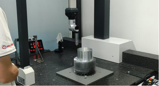
Importance of Contact Probes in Five-Axis Impeller Inspection
Five-axis impeller machining is technically complex, with curved complex surfaces, multi-blade construction, and small radii transitions, which place extremely high demands on machining precision. To effectively control these complex geometric features, precise measurement is crucial in both machining and inspection. Contact coordinate probe systems with high accuracy and work convenience have become indispensable tools in five-axis impeller machining inspection. Through real-time measurement and feedback, probes not only directly impact the optimization of the machining process but also effectively reduce the defect rate caused by machining faults. Therefore, ensuring the normal use of probes and reliability of measurement data has become an urgent problem within manufacturing circles.
Standards for Probe and Instrument Selection
In impeller measurements, rational selection of probe types and instrument specifications is a critical connection to ensure measurement accuracy and smooth running of the measurement process. Different measurement tasks have different demands on probe size, stiffness, and instrument performance. Therefore, probes and extension rods must be reasonably selected according to impeller geometric parameters and demands of measurement accuracy and related standards should be set to provide strong support for efficient measurement.
Probe Types and Specifications
Five-axis impeller machining typically involves complex surfaces and different size ranges, so appropriate contact probes should be selected accordingly. Generally speaking, spherical ruby probes are suitable for most impeller measurement applications due to their high-wear resistance and high-accuracy measurement capability. The probe diameter to select should correspond with spatial constraint and feature sizes of the measurement (position). For example, 1–3 mm probes can be used for the small corners of blades and roots, but 5 mm probes are best for big blade surfaces.
Probe Length and Rigidity
The stiffness and length of the probe immediately affect measurement stability and accuracy. During extension rod selection for probes, proper stiffness is necessary to avoid measurement error from vibration or bending when taking measurements. Carbon fiber or titanium alloy extension rods have low weight and high stiffness and therefore ensure proper measurement stability and accuracy.
Operation Specifications and Measurement Process Standards
In a bid to ensure repeatability and accuracy of impeller measurement, rigorous operation procedures and measuring standards must be put in place. All processes ranging from machine tool calibration, probe calibration up to path planning must be involved in this process and provide safe assurances for seamless implementation of measurement.
Machine Tool Calibration and Probe Calibration
Before impeller measurement, the test tool of equipment for measurement must be completely calibrated in terms of positioning accuracy and linear and rotary axis repeatability, spindle-rotary axis coaxiality, and perpendicularity so that the measurement reference and coordinate system are accurate. This avoids measurement errors caused by equipment defects. At the same time, probes also need to be calibrated using standard spheres or gauge blocks to accurately obtain probe radius compensation and direction vectors of measurement, in order to achieve high consistency of probe geometric parameters and measurements, and provide the foundation for measurement accuracy.
Measurement Environment and Condition Control
The measurement environment exerts a great impact on measurement results, so temperature, humidity, and measurement location cleanliness should be strictly controlled. It is recommended to maintain the measurement room temperature at (20±1)°C and humidity at 45%–65% to avoid thermal expansion-contraction or humidity change-induced dimension measurement errors. Before measurement, the impeller surface should be cleaned up in advance to eliminate potential oil spots, chips, and coolant, reducing the influence of impurities on contact surfaces of probes, creating good contact conditions between the probe and workpiece, improving the stability and reliability of measurement.
Probing Strategies and Path Planning
For measurement work on impeller complex spatial surfaces, measurement paths and strategies should be well planned based on impeller geometric features and design drawings prior to measurement so that measurement points are able to fully cover the key feature areas of the impeller. The measurement path should be interested in key regions such as blade tips, blade roots, trailing edges, and leading edges of the blade in a manner such that the points of measurement are uniformly spread to represent the curvature and impeller shape accurately. In designing the path, aside from the interaction between the probe and blades in space, normal contact measurement techniques should be used to the greatest extent to reduce the influence of probe lateral force on measurement accuracy, avoid probe offset or damage from probe-blade interference, and ensure measurement data integrity and accuracy.
Data Processing and Error Control Standards
So that measurement data is actually able to convey the geometric characteristics and machining accuracy of impellers, perfect data processing and error control needs to be applied. Not only does this help to improve the efficiency and traceability of measurement data but also provides an essential basis for follow-up quality analysis and process optimization.
Data Filtering and Error Compensation
In measurement, the collected data will always be subject to some external interferences such as mechanical vibration, probe error, temperature-humidity fluctuation of the environment, etc., which can cause random and systematic errors. Therefore, filtering and denoising treatment has to be performed on measurement data, for example, using moving average filtering, Gaussian filtering, etc., and other algorithms to suppress the effect of fortuitous errors on measuring curves. At the same time, in order to offset measurement deviations resulting from probe ball diameter thermal drift, the corresponding compensation algorithms must also be used to preclude the effect of the probe’s thermal expansion-contraction on the measured result using the calibration models, in order to improve the measured data.
Deviation Analysis and Closed-Loop Traceability Mechanism
Comparison of measurement data objectively to the design model is an important method to identify geometric deviations. With automatic comparison analysis software, the deviation distribution between design data and measurement data for each section can be visually provided to allow engineers to identify the machining errors and potential quality hazards in a timely fashion. Where measured values lie outside the specified tolerance range, the following closed-loop correction process should be initiated: one end, feedback deviation information to machining programming and on-spot staff for tool path optimization, cutting conditions, or clamping placement; the other end, detail pertinent information and adjustment measures in the quality database, providing traceable experience references and continuous improvement foundation for subsequent manufacturing of identical or similar products, forming a complete, effective, and traceable quality management closed loop.
Measurement Result Confirmation and Recording Standards
The entire measurement data, analysis report, and operation process shall be completely recorded, e.g., probe model, calibration information, measurement approach, operator, etc., and the aforementioned data must be incorporated into the quality management system. These procedures not only guarantee traceability for measurement results but also provide data support for subsequent process optimization and precision improvement.
Conclusion
Contact coordinate probe systems are increasingly applied in five-axis impeller machining inspection, and accuracy and reliability are vital to guaranteeing optimal machining process and improving final product quality. By establishing a complete set of usage standards such as full-process control from probe selection, operation specifications, environment control, data processing to result verification, the accuracy and stability of impeller machining inspection can be greatly improved. On the other hand, implementation of these standards not only helps with enhancing credibility of measurement data, but also provides important support to enterprise production management and technology renewal. With development in technology and continuous improvement in measurement technology, it is believed that contact coordinate probes will play a greater role in the impeller machining industry and provide a strong guarantee for precision machining in the manufacturing sector.


