
Complicated impellers are widely used in significant machinery such as aero-engines, superchargers, high-performance pumps, and turbomachinery. Their geometric models are usually free-form surfaces, thin channels, and high-curvature surfaces, which bring serious challenges to CNC machining. How to improve programming efficiency and machining stability with high accuracy has been a key issue in the industry. As a mature CAM platform, Mastercam has strong modeling, tool path generation, and multi-axis linkage features, especially its “Blade Expert” module, optimized for machining intricate impeller and blades, with effective and precise tool path generation functions.
Introduction
With advancing high-end manufacturing technologies, complicated impellers have increasingly assumed key functions in power systems, and high-precision manufacturing of impellers is directly related to the overall machine’s efficiency, dynamic balance capacity, and long-term operational reliability. Under multidegree-of-freedom spatial surfaces such as impellers, classical CAM programming will generally suffer from discontinuous tool paths, path interference, and overcutting when it comes to machining. From day-to-day project experience, I deeply realize that with the assistance of Mastercam, especially its “Blade Expert” module, programming efficiency can be remarkably increased, while skillfully controlling tool posture and tool path continuity, and thereby increasing general machining quality by a great margin. Therefore, reasonably planning a scientific and efficient Mastercam programming program is a significant assurance for promoting high-precision manufacture of complex impellers.
Preparation Work Before Tool Path Programming for Complex Impellers
Five-axis machining of complicated impellers puts extremely high demands on tool path programming. Proper preparation work is the key assurance for smooth machining. Through high-quality model processing and reasonable coordinate system planning, collision risks and resulting path adjustment can be minimized effectively, improving programming efficiency and machining quality.
Model Import and Geometric Cleaning
The first step in the tool path programming process is to import the 3D model, usually from CAD programs (e.g., NX, CATIA, SolidWorks, etc.). After importing into Mastercam, the model needs to be thoroughly cleaned out, such as the deletion of overlying surfaces, geometric gap repairing, and surface continuity optimization, more particularly the closing of the leading edge, trailing edge, and hub of the blade. Although this process is laborious, it directly affects tool path generation accuracy and follow-up simulation process stability. Even a negligible geometric flaw leads to simulation anomalies or even actual machining flaws.
Machining Coordinate System Setting and Tool Axis Direction Planning
Depending on the structural configuration of employed five-axis machine tool (e.g., cradle type, platform type) and the clamping method of fixture, the definition of workpiece machining coordinate system and program zero is significant. This not only provides a spatial reference point to the programming but also forms a foundation for future tool axis posture control. Accurate layout of coordinate systems can simplify the adjustment of tool angles, virtually eliminate machine tool interference, improve machining safety and continuity of paths, and enable smooth cutting of complex impellers.
Tool Path Programming Strategies Based on Mastercam
Being intricate 3D surface constituents, machining path planning for impellers immediately influences machining quality and efficiency. With capabilities of robust tool path generation and multi-axis linkage in Mastercam, intelligent and efficient programming for the intricate shape of impellers can be realized. Rational strategy selection of roughing and finishing and tool axis posture optimization, in addition to ensuring machining quality, also effectively extends tool life and reduces production costs.
Roughing Tool Path: Dynamic Milling Strategy
In the initial process of roughing intricate impellers, I recommend using Mastercam’s “Dynamic Milling” tool path strategy. Dynamic Milling avoids air cutting and reduces tool wear successfully by adaptive step pitch, constant cutting load management, and path optimization. Where there are narrow passages between two or more blades, dynamic tool paths can intelligently skip around blanks, thus improving material removal rate as well as safety during machining.
Finishing Strategy: Surface Fitting and Streamline Control
In completing impellers, we must balance surface finish and blade precision. Mastercam provides a list of strategies including “streamline machining”, “projection machining along curves”, and “equal step angle cleaning machining”. In the projects I have worked on, streamline strategy is best applied for thick leading edge change blades, with the benefits of ensuring tool path continuity and preventing commutation vibration. It is recommended to assign independent tool paths for the fillet and hub components to offer more refined machining quality control.
Multi-Axis Linkage Programming and Tool Axis Control
Multi-axis tool path generation is the key to dealing with challenging surfaces of impellers. Mastercam tool path modules such as “Morph between two surfaces” and “Parallel to surface” support automatic tool posture adjustment for smooth continuous transition of the tool axis and surface normal. Tool axis smoothing, forward angle, and side angle can also be specified at the time of programming, which are of significant practical utility especially for collision avoidance and edge directionality maintenance. I myself prefer to integrate multi-axis approaches with geographical layering in order to enhance program controllability without over-controlling complexity.
Tool Path Simulation and Process Parameter Optimization
For five-axis machining of intricate impellers, tool path simulation and process parameter optimization are the critical connections in the chain in order to ensure machining safety and quality. By virtual simulation of the cutting process and scientific optimization of cutting parameters, trial cutting and adjustment expense as well as tool breakage and workpiece scrapping by program errors or erroneous parameters can not only be prevented, but this can be done efficiently. Proper pre-simulation and optimization work is, therefore, a required prerequisite for executing accurate and efficient production.
Tool Path Simulation and Collision Detection
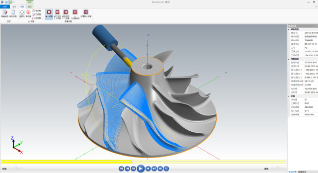
After the initial generation of the tool path, I always ensure that I perform a complete virtual simulation process before it. Through the real machine tool simulation feature in CAM software such as Mastercam, all potential interference and collision risks such as the spindle head, worktable, fixture, and workpiece can be identified. The process is especially suited for parts of intricate configuration and constricted areas such as impellers. Through dynamic showing of tool trajectory and synchronization of all motion axes, not only can prevention of tool axis contact over-travel and surface offset of the contact surface be ensured ahead of time, but also a secure and efficient foundation for tracking and executing real machining is established.
Setting and Adjusting Cutting Parameters
Cutting characteristics of different materials are rather different (such as Inconel, high-strength titanium alloy, stainless steel), and thus cutting parameters must be determined with a definite objective. When I am finishing, I keep an eye on the rational correspondence between cutting speed, feed rate, spindle speed, and cutting depth, and make reference to recommended data from tool suppliers, and (tentative adjust) continually during the simulation of cutting. For example, for harder Inconel, choosing low cutting speed and small depth of cut can inhibit cutting heat accumulation; for titanium alloy, medium cutting speed and high cooling capacity method should be chosen to reduce thermal effect and surface harm in cutting. Combining simulation analysis with cutting tests, the tool life can significantly be extended, and machining surface quality can be improved.
Advantages of the “Blade Expert” Module in Practical Applications
Mastercam’s “Blade Expert” is designed with especial precision for delicate impeller parts, where whole tool path modules for roughing, finishing blades, hubs, and fillets are combined. It identifies areas of models automatically, quickly sets up limits, and automatically attains avoidance of interference areas and transition by employing tool axis control strategies. I have used this module to complete batch programming in a number of multi-blade impeller projects, which dramatically improved programming efficiency and path quality. Its built-in functions such as “point distribution optimization”, “automatic tool axis smoothing”, and “automatic forward tilting in collision areas” are especially suited to high-density blade structures, avoiding the headache of too much parameter adjustment and trial-error in traditional programming.
Apart from that, the module also supports unified simulation and NC output, and it can be docked to the actual machine tool machining path directly without any issues, greatly reducing debugging time and test piece scrapping rate.
Conclusion
With the analysis and engineering experience sharing in this paper, it can be seen that the Mastercam-based complex impeller tool path programming method not only has high efficiency, intelligence, and high controllability but also has a systematic solution to complex free-form surface machining. Especially in the current manufacturing scenario involving high precision and high automation requirements, the tool path planning ability provided by Mastercam enables programmers to be more flexible and involve a lower error rate.


