
As a crucial component of fluid machinery, the tooth profile accuracy of an impeller will directly affect the aerodynamic performance, energy efficiency, and operating stability of equipment. As the structural complexity of impellers increases and manufacturing technologies become more advanced continuously, the traditional measurement methods can no longer meet the higher demand for accuracy control. High-precision CMMs, characterized by high resolution and three-dimensional full space measurement by non-contact or micro-contact techniques, have been major equipment for testing impeller tooth profile error and accuracy control.
Introduction
As an important component of most fluid mechanical machinery, the tooth profile accuracy of an impeller will directly impact the aerodynamic performance, running efficiency, and vibration stability of the machinery. Particularly in high-performance machinery such as compressors, fans, water pumps, and aero-engines, minute tooth profile deviations can lead to airflow separation, efficiency loss, or even structural resonance, ultimately causing impeller failure or equipment malfunction. Traditional measurement methods are faced with many challenges in measuring the tooth profiles of intricate free-form surface impellers, such as poor measurement accuracy, lengthy measurement time, and inability to efficiently evaluate the integrity of the profile.
With uninterrupted advances in manufacturing technology, such as the development of five-axis (linkage) machining and additive manufacturing technologies, impeller-making processes have been increasingly sophisticated, and tooth profiles are found to exhibit free-form surface structures with many boundaries. In such contexts, high-precision coordinate measuring systems (CMMs) have become the main equipment for measuring impeller tooth profile errors and accuracy control. The present paper will focus on the application of coordinate measurement in accuracy control of an impeller tooth profile, e.g., datum modeling, error analysis, and closed-loop control by data feedback.
Importance of Impeller Tooth Profile Accuracy Control
An impeller’s tooth profile contour in high-performance rotary machinery, as the main component, is not only related to the global aerodynamic efficiency but also heavily affects assembly matching, fatigue life, and dynamic balance. With the impeller evolving towards high speed, minute clearances, and complex multi-stage structures, tooth profile accuracy is not any ordinary tolerance control issue but a critical control index within the entire process of design-manufacturing-inspection. The following four points thoroughly demonstrate that the precision control of impeller tooth profile plays an important role.
Fundamental Guarantee for Aerodynamic Performance
The main function of an impeller is to guide the airflow in order to form compression or expansion movements along the desired trajectory. The tooth profile lines, inclination angles, and contour accuracy of an impeller directly determine the airflow guide angle, velocity distribution, and pressure gradient. Minor tooth profile deviations (e.g., 0.02mm tip deviation) can lead to aerodynamic non-uniformities such as boundary layer separation, secondary eddies, or even local shock waves, thus affecting the efficiency and stability of the overall compressor or turbine system. Especially in pressure ratio sensitive units such as aero-engines and gas turbines, tooth profile precision is the assurance of an organized flow field and stable thermodynamic cycle. Accurate tooth profiles therefore are not only a geometric issue but also a critical aerodynamic performance criterion.
Assembly Matching and Multi-Stage Linkage Coordination
Impeller arrangements generally adopt multi-stage connecting arrangements, and tight radial and axial fits among the stages are required for energy conversion and flow field connection. If profile machining error in the tooth exists, i.e., undercut at the tooth root or asymmetry of tooth sides, it will lead to abnormal inter-stage clearances or gear interference, affecting assembly accuracy and working coordination. In addition, during high-speed operation, assembly interference will cause friction heat, mechanical noise, or even blade fracture, posing a serious threat to equipment safety. During the high-speed compressor project on which I worked, a tooth profile deviation of only 0.03mm resulted in inter-stage interference, finally in rework. Due to these reasons, tooth profile error control is not only a manufacturing issue but also a primary assurance for assembly reliability and system coordination.
Extending Fatigue Life and Suppressing Crack Sources
Local geometric abrupt changes due to errors in tooth profiles easily become sources of crack initiation and stress concentration points. Especially under service conditions of high temperature, high speed, and high load, irregular tooth root or tooth side curves will induce micro-cracks, which will propagate rapidly with cyclic loads and result in premature fatigue failure. Fracture surface analysis shows that initiation points of most of the failed impellers are precisely where there are positions of geometry contour abrupt changes or distortion of tooth profile. Therefore, one of the key measures to effectively enhance the fatigue life of impellers is precisely controlling the tooth profile in a way that ensures continuity and least contour error.
Dynamic Balance Optimization and Manufacturing Closed-Loop Control
Dynamic balance performance is a very important parameter of establishing the stability of rotating components, and tooth profile errors are most frequently serious sources of non-uniform mass distribution. Tooth profiles that are very accurate not only reduce asymmetric mass distribution to a minimum, but they very significantly lower eccentric moments, increasing overall operational stability. High-end manufacturing data of tooth profile measurement is typically used to offset the machining path of the CAM system, achieving a close loop of “measurement-compensation-control” to promote the level of dynamic balance. For example, in the optimization project of finish milling of a turbine, through online comparison of tooth profile contour and automatic compensation, the dynamic unbalance was reduced from the initial 0.7 g·mm to 0.2 g·mm, fully meeting the requirement of high-speed running.
Application Methods of Coordinate Measurement in Impeller Tooth Profile Detection
As the geometric complexity of impellers increases, two-dimensional measurement methods are insufficient to meet demands for a precise evaluation of free-form surface tooth profile accuracy. Coordinate measurement technology (CMM) with high precision, multi-axis linkage, and flexibility of measurement is becoming the core tool of tooth profile detection, especially in fields of application in high-performance aircraft, energy machinery, and precision fluid machinery. Apart from the geometrical completeness of error detection, its merits also reside in its ability to realize closed-loop production and quality control.
Datum Modeling and Measurement Path Planning
The high-precision measurement requirement is an optimized measurement path and a geometric datum model with high accuracy. For actual applications, measurement engineers import the CAD model of the design to the CMM system at the start and establish a three-dimensional datum coordinate system based on tooth profile characteristics, clamping condition, and probe type of the impeller. Through utilization of path planning software (e.g., PC-DMIS, Calypso, etc.), the measurement system can program probe paths across the model contour and execute point-to-point measurement or scanning of the contour line in a continuous mode. Especially when measuring impellers with slight differences between more than one blade, the system is also able to accomplish parameterized path planning, which greatly improves the measurement efficiency and flexibility. The path simulation function can detect probe interference risks in advance to avoid unintentional collision during measurement.
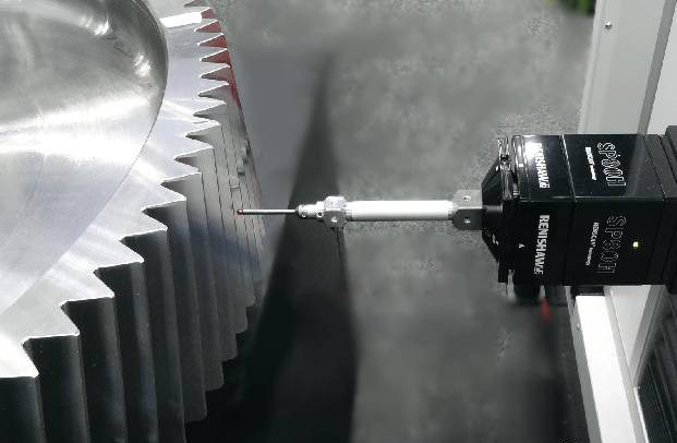
Data Acquisition Technology for Free-Form Surface Tooth Profiles
Impeller tooth profiles are likely to have complex free-form surface shapes, such as spiral surfaces, hyperboloids, and variable-section curves, which put more stringent requirements on measurement accuracy and probe control. To meet the high-resolution point cloud data acquisition requirement, CMM systems use mainly scanning probes (e.g., RENISHAW SP25, HP-S-X1, etc.) for continuous sampling. For extremely minute or highly reflective surfaces for which contact measurement is not suitable, laser scanning or white light interferometry systems may be used to accomplish non-contact three-dimensional reconstruction, which not only avoids contact probe deformation risk but also enhances the efficiency of measurement. For example, when measuring small titanium alloy impellers below Φ80 mm, blue light scanning can achieve tooth profile data acquisition with precision of 0.005 mm in order to meet the requirements of surface shape testing for complex shapes.
Analysis and Evaluation Methods for Tooth Profile Errors
The high-density point cloud data obtained through coordinate measurement can be compared with the CAD model to obtain a set of meaningful error indicators like contour deviation, normal deviation, local runout, asymmetry, and spiral error. Color difference maps or contour deviation maps (Profile Deviation Map) widely used to inherently express geometric differences between actual tooth profile and theoretical model are used. Let us take the maximum deviation value of contour deviation as an instance. It is used primarily to determine the degree of tooth profile quality; while normal error can be used to evaluate the precision of machining tool feed direction control. In addition, measurement data can be more used for statistical processing, such as pass rate distribution and local abnormal points of aggregation detection, to assist engineers in the optimization of tool paths and process parameters.
Measurement Result Feedback and Closed-Loop Manufacturing Control
Coordinate measurement’s greatest value apart from “measurement” is also “control”. Coupled with the CAM system, CMM has the potential to give real-time measurement feedback, which can be used as a basis for path correction in numerical control machining to create a closed-loop of the entire process of “design-machining-measurement-correction”. For example, in finish milling of an aero-engine impeller, as soon as measurement results are sent to the CAM system in real-time, the tool compensation mechanism automatically will come into play, effectively eradicating tooth profile deviation accumulation with batches, and finally improving tooth profile consistency to as low as ±0.015 mm. This closed-loop control concept is gradually being used in digital factory building as well and is the fundamental underpinning for future intelligent development of impeller production.
Analysis of Typical Cases
One typical case is a titanium alloy impeller of an aviation compressor, whose tooth profile precision requirement is very high (tooth surface error has to be controlled within ±0.015 mm). After the initial machining, a coordinate system is imposed to extensively scan and measure the tooth profile of the impeller. Based on the analysis of the measurement data, it was found that the contour tolerance of the root of certain blades was more than the standard by 0.025 mm, mainly owing to errors caused by local tool deflection and path interference. Following the measurement feedback guidance, the engineers adjusted the machining path and carried out the local correction. Following the secondary machining, the tooth profile error was controlled at ±0.009 mm, meeting the design accuracy requirements.
In addition, the measurement data was also imported into the dynamic balance analysis system, providing reliable data support for impeller dynamic balance optimization. Based on this closed-loop control process, the impeller manufacturing quality was effectively guaranteed.
Conclusion
The application of high-precision coordinate measurement technology to the accuracy control of impeller tooth profiles is an indispensable integral link in modern manufacturing. Apart from improving measurement accuracy and efficiency, it greatly enhances the quality of impeller manufacture using closed-loop control and feedback data. With the development of intelligent manufacturing and digital measurement technology, the coordinate system will play an even greater role in future impeller manufacturing and promote the advancement of impeller manufacturing towards higher precision, higher consistency, and higher intelligence.


