
As high-performance impellers are in demand in the manufacturing industry, the structure of impellers is also becoming more complex, and demands on CNC systems to machine them are greater. Three-axis CNC systems have not been adequate in coping with problems of machining issues such as spatial free-form surface and multi-directional changes in curvatures. Five-axis and higher multi-axis CNC machines have increasingly become the mainstream technology for machining complex impellers due to their spatial mobility and high-precision capability of linkage control.
Introduction
In aero-engines, gas turbines, and high-performance fluid machinery equipment, impellers, being key energy conversion components, their geometric accuracy and surface quality determine the machine performance in general. New-type impellers have obvious free-form surface characteristics: variable cross-sections, bidirectional bending, asymmetric flow passages, etc. Their machining no longer relies on simple three-axis linkage, but requires a machining process with high flexibility and multi-degree freedom.
In actual projects, there was once a precision machining process of a certain type of high-pressure compressor impeller, which has severe curvature changes and more than one transition surface. Traditional three-axis machining not only requires complex path planning and high-frequency machining interference but cannot meet the technical demands of surface roughness and profile error. Following the application of a five-axis CNC system, high efficiency and quality machining objectives were attained through real-time attitude adjustment and linkage control. This also led to my deeply appreciating the necessity of multi-axis systems in the production of complex structures.
Composition and Function Analysis of Multi-Axis CNC Systems
A traditional multi-axis CNC machine has three linear axes (X, Y, Z) and two rotating axes (such as A and C axes) with a five-axis linkage structure composed of three linear axes and two rotary axes. Modern CNC platforms (such as FANUC 31i-B5, Siemens 840D sl, Beckhoff TwinCAT, etc.) utilize high-performance processors and real-time control cores with the following functional modules:
- Multi-axis interpolation calculation module: Examines complex surface paths into distinct axis instructions in real-time;
- High-precision synchronous controller: Synchronizes the concurrent operation of each axis with a shared time axis to ensure correct control of the tool path;
- Attitude control and RTCP (Rotation Tool Center Point) module: Automatically calculates the best tool direction-workpiece contact point relationship;
- Error compensation mechanism: Dynamic error correction of geometric errors, thermal drift, and servo system delay;
- Adaptive control and feedforward algorithm: Improve response performance and system stability in acceleration phase.
- Especially in synchronous control, the system achieves strict consistency in sending command and executing all axes with a unified scheduling clock in the controller, which makes trajectory tracking accuracy increase by a vast margin.
Analysis of Key Points in Synchronous Control Technology
With extensive use of sophisticated impeller geometric structures in five-axis CNC machining, higher requirements are put on the synchronous accuracy of CNC systems. The multi-curvature, spatial torsion, and continuity of smooth surface of impellers mean that their machining trajectories are very sensitive to the accurate coordinated motion of multiple axes. Synchronous control not only provides the foundation for achieving high-quality cutting paths but also the essential linkage to ensure machining efficiency, avoid tool overload, and reduce surface residual textures. For this vital issue, there has been a long history of trend in innovation in modern high-end CNC systems in terms of interpolation strategies, timing control, attitude algorithms, and error compensation for building a multi-dimensional cooperative control system.
Construction Logic of Multi-Axis Coordinated Interpolation Algorithms
In five-axis machining, interpolation algorithm is the first critical checkpoint in achieving precise tracking of spatial paths. The NC codes produced by mainstream CAM software currently available (e.g., Siemens NX, Autodesk PowerMill) need to be further dissected into linkage traces of every axis by the controller. Interpolation accuracy and stability therefore have an immediate effect on the cutting effect. The non-uniform rational B-spline (NURBS) interpolation with excellent curvature continuity performance has been the preferred algorithm of choice for complex surface machining with capability to effectively constrain tool vibration caused by sudden path change. The quintic spline interpolation, in addition to keeping the path smooth, also confines the peak acceleration to a significant level, extending the mechanical life. Upon debugging the Siemens 840D platform, I found that by optimizing the interpolation cycle to 2 ms and setting it with quintic spline and 6-segment pre-reading buffer mechanism, the path breakpoints in the transition section of the impeller were significantly decreased, and the overall continuity of machining was significantly improved.
Time Synchronization Strategy Based on a Unified Clock
Time synchronization control is the synchronized scheduling center of simultaneous movement of multiple axes, especially in high-speed and high-precision, which has a decisive influence on the continuity of machining paths. With the establishment of an average clock system to ensure all interpolation axes moving in the same cycle, path deviation caused by time drift can be eliminated. In addition, feedforward compensation technology constructs a speed curve with the current and estimated speeds of the spindle and pre-compensates the error of displacement, further improving timeliness and robustness of synchronous control. In the real-world operation of the Siemens S7-1500 + SINAMICS S120 platform, with master-slave axis time synchronization and speed feedforward correction, the trajectory error in the corner area of an aircraft turbine impeller was condensed from the original 0.6 mm to less than 0.2 mm and showed outstanding control response capability.
Attitude Control and RTCP (Rotation Tool Center Point) Compensation
One of the distinctive issues of five-axis linkage machining is tool attitude change-induced path offset. RTCP technology, due to the real-time tool tip compensation function, ensures that the change of rotation of tool attitude does not lead to cutting point position drift. The function is an indispensable role in ensuring the quality of surface machining. At the same time, modern controllers also have built-in tilt angle limits and singularity avoidance capabilities to prevent over-limit or trajectory interrupt in attitude rotation. The tool tip coordinate-to-inclined workpiece surface linkage control is implemented by using FANUC commands G43.4 and G68.2 simultaneously in the FANUC five-axis system. When cutting the blade root structure with intricate inclined surfaces, it really dampens the chatter marks owing to sudden changes in tilt angle and improves the ultimate surface quality.
Error Modeling and Online Compensation Technology
Synchronous accuracy is affected by various errors:
| Error Type | Source | Compensation Method |
| Geometric error | Rotation center offset, guide rail non-straightness | Establish geometric models, feedforward compensation |
| Thermal error | Structural deformation caused by thermal expansion | Temperature model + real-time compensation with thermal sensors |
| Servo error | Motor lag, load change | PID + model prediction + adaptive adjustment |
With the integration of high-bandwidth feedback from today’s advanced control systems and temperature sensor networks, thermal-force coupling compensation with high consistency between the workpiece geometry and tool path is possible.
Practical Application Cases and Technical Implementation
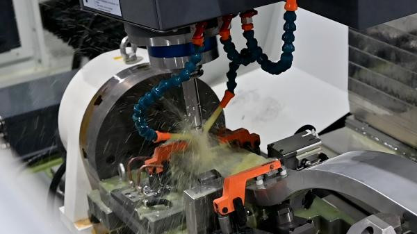
The Makino D500 five-axis machining center with Siemens 840D sl control system was implemented by an aeronautical company during the machining of high-pressure compressor impellers. The entire machining process reflects the essence of the synchronous control technology advantages:
- Path generation: Equal curvature layer cutting + quintic spline interpolation;
- Attitude control: Let RTCP keep tool tip position stable;
- Error compensation: Apply online geometric compensation tables and thermal drift compensation functions;
- Machining effect: Ra is better than 0.8μm, profile error is less than ±0.02mm, meeting the assembly-level standards of aviation components.
Process Improvements Brought by Synchronous Control
| Control Element | Process Effect |
| Multi-axis synchronous interpolation | Improve trajectory consistency, avoid tool interference |
| Real-time attitude adjustment | Improve surface consistency and finish |
| Thermal and servo error compensation | Maintain long-term stable machining accuracy |
| Time axis synchronization mechanism | Improve the response quality of machining corner areas |
Together with real-time Ethernet protocols such as EtherCAT and synchronous event scheduling mechanisms (such as ADI’s TCU + TRU architecture), the synchronization domain extends from the controller to the driver I/O level, and it makes a quantum improvement in control accuracy.
Conclusion
Synchronous control technology of multi-axis CNC machine tools is more and more becoming the backbone support technology for machining of complicated impellers. Based on high-degree-of-freedom coordinated interpolation, steady attitude control, and adaptive error compensation, five-axis and higher CNC platforms can well deal with all kinds of challenges in machining of complex surfaces. As a mechanical processing automation project engineer who has been committed to for years, I deeply know the close relationship between synchronous control accuracy and machining quality.


