
As the key rotating components with complex configuration and extremely high precision requirement, impellers are faced with challenges of free-form surface contour control, flow channel interference avoidance, and double constraints of machining efficiency and surface quality in machining. To improve machining efficiency and precision, multi-tool path coordinated machining technologies have been an increasingly prominent trend in the production of complex impellers.
Introduction
Complex impellers, being a typical 3D free-form surface structure component, are widely used in devices like aero-engines, gas turbines, turbochargers, and precision water pumps. Their geometric features—thin wall, big curvature change, dense multi-blade arrangement, and narrow flow passage—make their machining one of the most challenging tasks in CNC machining. Traditional single-tool machining techniques have to make a trade-off among machining efficiency, surface finish, and contour accuracy due to limitations in tool geometry, machine tool rigidity, and machining posture optimization.
Having had several experiences of being involved in five-axis machining projects of impeller parts, I have keenly felt the limitations of single-tool paths at areas of abrupt curvature changes such as blade tips and roots. With the evolution of CAD/CAM technology and the growing popularity of multi-axis high-end CNC equipment, process strategies based on multi-tool path coordination have gradually emerged. By means of division of labor and cooperation with different types of tools in different areas, the machining quality can be significantly improved, and the dynamic response capability of the machining process can be optimized. Starting with the reasoning of path division, the article introduces the primary technologies of multi-tool path coordination and verifies its feasibility and process value through representative examples.
Logic of Multi-Tool Path Division in Impeller Machining
The foundation of multi-tool path coordination is modular separation of impeller structural features and machining operations. In traditional machining flows, roughing, semi-finishing, and finishing operations sequentially carry out tasks of cutting large allowances, establishing basic contours, and improving surface quality, while different structural zones (e.g., blade roots, blade bodies, blade tips, flow channels, hubs) are supported by different tools and path strategies based on their geometric characteristics.
- Roughing Stage: The main aim is to remove materials quickly and remain sufficient machining allowances. It often uses large-diameter flat-end mills or barrel cutters (Φ12–Φ20 mm), along with multi-axis side milling or trochoidal milling strategies for high-efficiency machining. For flow channel areas in blades, due to narrow channels and tight blade spacing, roughing often uses slot milling or plunge milling strategies to avoid tool interference.
- Semi-Finishing Stage: Tactics must be modified based on the curvature and three-dimensional topography of each zone. For example, blade root transition areas have small curvature radii and limited space, which are suitable for five-axis inclined interpolation with Φ4–Φ6 small ball cutters; blade body areas have smooth surface and fine continuity, which are suitable for spiral envelope cutting using barrel cutters; blade tip areas have large curvature change, which requires multi-segment finishing paths with small-diameter ball cutters to ensure surface evenness and contour closure.
- Hub-Blade Junction Areas: In the face of high geometric complexity and high requirements for machining continuity, path planning must fully consider the smoothness of posture transition to prevent local stress concentration or residual areas that are not cut.
This idea of tool path coordination based on structural decoupling and process stage division lays a solid foundation for subsequent path fusion and error control.
Key Technical Elements of Multi-Tool Path Coordination
Five-axis machining of complex structural parts like impellers involves multiple tools that typically cooperate to complete roughing and finishing operations in steps and areas. Coordinated control between multi-tool paths is particularly crucial for geometric consistency and surface continuity in machining. From tool selection and attitude optimization to path connection and error compensation, collaborative accuracy of each link directly influences the final machining quality and process efficiency.
Tool Selection and Posture Matching Optimization
Reasonable tool selection is the foundation of coordination in multi-tool machining systems, especially for the situation of impeller blade processing with complex free-form surfaces. In my previous practice, ball-end mills possess stable performance in 3D surface point milling due to their point-contact characteristics, while tapered cutters achieve higher machining rigidity and forming efficiency in high-curvature areas of surfaces. Besides, barrel cutters, due to their special contour geometry, can achieve “wide stepover, high-quality” machining effects in five-axis tilting milling processes, so they are particularly suitable for finish machining operations. Currently, CAM software (e.g., HyperMILL, NX) generally has automatic posture adjustment capabilities to maintain a constant inclination or normal angle, achieve optimal contact point distribution, efficiently avoid excessive machine tool swings, and enhance machining smoothness and stability.
Path Connection and Transition Smoothness Control
Multi-segment path splicing or tool change transition areas are prone to trajectory discontinuity and “tool jumping.” These interferences not only easily create surface step marks and vibration marks but also can make the material harder due to local instantaneous high loads, affecting subsequent finishing results. Therefore, when programming with HyperMILL or NX systems, I prefer to adopt a “contour + spiral” hybrid trajectory strategy, combined with dynamic acceleration/deceleration interpolation technology for the creation of tool approach/retract continuous speed curves and reduction of mechanical (shock). Under a three-axis machining strategy of A-axis locking, the spatial direction of the tool retraction path must also be under control to possess some directional consistency with the re-approach path to avoid unstable cutting caused by sudden posture changes.
Error Coordination and Compensation Mechanism Between Tools
In multi-tool collaborative machining, there are a number of tools that will alternately cut the same area, so the geometric overlap areas are highly likely to accumulate errors. To ensure machining consistency at area boundaries, dynamic correction must be achieved through the tool compensation function of the CNC system. Thus, for example, in FANUC systems, precise axial control can be achieved with G43 H-number length compensation instructions, and in Siemens systems, radius and length can be synchronously controlled by D-number binding with the tool library. Additionally, it is recommended to detect on a regular basis with online probes or tool setters and update compensation values through a tool offset database. In my view, the construction of a standardized “tool compensation management database” is the foundation of the high-precision operation of multi-tool path systems, not only improving stability but also laying the groundwork for the follow-up path automation and compensation closed loops.
Programming Platform Integration and Interference Simulation Support
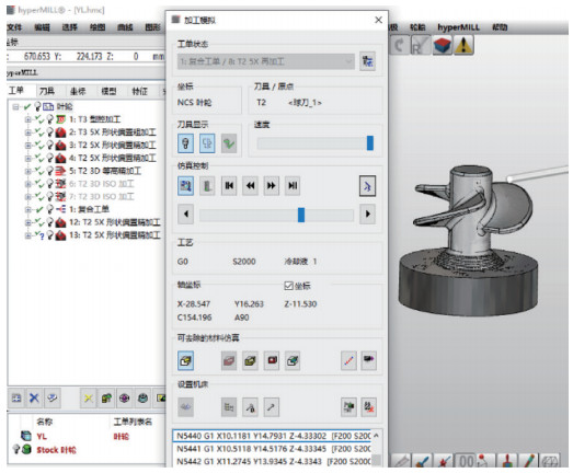
Leading-edge mainstream high-end CAM software (e.g., PowerMILL, HyperMILL) has widely adopted multi-tool path nesting methods and machine tool interference simulation modules. Through the predefinition of machine tool digital twin models and coupling with machining simulation engines, users can anticipate machine tool posture constraints, stroke limits, tool holder interference areas, and fixture/workpiece collision points before path generation. Taking my own operational experience as an example, through the (linkage) function of machine tool and tool models in HyperMILL, a fixture interference problem caused by C-axis rotation was successfully avoided in a collaborative machining project using multiple tools, and path optimization and process assurance were achieved without physical machine trial cutting. These simulation techniques not only increase programming effectiveness but also significantly reduce trial-error costs on site, and hence they are a crucial link in current multi-tool intelligent path planning.
Typical Case Analysis and Data Verification
In a project, I participated in the development of a multi-tool machining scheme for an Inconel 718 aircraft compressor impeller, the key parameters of which are: Φ160 mm outer diameter, 18 blades, surface precision requirement Ra ≤ 0.8μm, geometric tolerance ±0.01 mm. We adopted the following multi-tool path coordination strategy:
| Area | Tool Type | Machining Strategy | Diameter/Radius | Coordination Strategy |
| Hub | Roughing flat-end mill | Multi-axis side milling | Φ16 mm | Extend to blade roots after machining |
| Blade Root Transition | Small ball cutter | Inclined five-axis interpolation | Φ6 mm | Ensure continuous transition with the hub |
| Blade Body | Barrel cutter | Spiral envelope machining | R4 barrel | Maintain constant inclination angle |
| Blade Tip | Small ball cutter | Multi-segment finishing path | Φ3 mm | Local repair and precise connection |
Machining Results:
- Total machining time reduced by 28% compared with the single-tool scheme;
- Surface roughness decreased from Ra 1.0μm to 0.65μm;
- Contour error controlled within ±0.008 mm;
- Tool life increased by approximately 25%, rework rate significantly reduced.
Process Implementation Suggestions and Optimization Directions
To ensure the steady and efficient use of multi-tool path coordination strategies in actual production, a comprehensive process implementation framework should be formed from multiple dimensions such as system standardization, path planning, measurement feedback, and operation specification. In a number of complicated impeller projects I participated in, the following five optimization measures are quite practical and reproducible.
Establish Standardized Tool Area Templates
At the initial phase of programming, establishing standardized “tool-machining area-path type” templates can significantly improve the path planning efficiency and consistency. For example, roughing paths can be set as large-diameter ball-end mills + contour cutting, semi-finishing as tapered cutters + spiral envelope methods, and finishing as barrel cutters + constant inclination milling. With the template management function of CAM software (e.g., NX, HyperMILL), engineers are able to reuse standard path modules quickly and edit locally, not just improving modeling efficiency but also reducing process fluctuations caused by variations in path structure.
Strengthen Path Simulation and Dynamic Interference Detection
Aiming at five-axis linkage machining complexity, full-dimensional simulation and interference detection mechanisms should be brought into the path generation process. Particularly, rotating axes’ posture limits, tool length, and fixture interference space need to be predicted to ensure path feasibility and machine tool safety. It is suggested to simulate paths with the help of ISV modules (for example, NX ISV, HyperMILL VSC) and enable dynamic tool interference checking for each path segment to revise illogical postures or machining sequences in time.
Unify Reference Systems and Path Data Specifications
To ensure the spatial coincidence precision between different tool paths, part coordinate systems, program origins, machine tool zeros, and tool compensation references should be consolidated. For example, in my duty aviation titanium alloy impeller project, “single main coordinate system + tool length compensation binding reference” strategy effectively avoided overcutting or undercutting caused by minimal coordinate differences between paths. It is recommended to define standard path output specifications and post-processing settings to achieve reference alignment among CNC programs.
Introduce On-Machine Measurement and Compensation Closed-Loop Mechanisms
Periodic feedback of actual tool length, wear offset, and key workpiece dimensions by on-machine measurement systems (such as trigger probes, laser tool setters) enables dynamic updating of path parameters and error closed-loop control. For high-precision blade areas, on-machine checking after roughing and before finishing, combined with G43/G41 compensation instructions in the control system for online adjustment, is recommended, thereby improving dimensional consistency and surface continuity.
Formulate Process Switching and Program Calling Specifications
Multi-tool paths have high program switching and tool changing frequencies, and unclear operation processes are highly likely to result in on-site human errors. Therefore, it is recommended to develop detailed process execution SOPs (Standard Operating Procedures) for tool number management, path sequence, program calling (e.g., G65 subroutine structures), and interference inspection key points. Combined with the control system’s tool life management and automatic tool change system, the operational error rates can be significantly reduced, and the overall implementation efficiency can be improved.
Conclusion
Multi-tool path coordinated machining technology not only realizes a process breakthrough in high-efficiency free-form surface machining but also deeply reflects a philosophy of precision manufacturing. Through the synergistic optimization of multi-tool combined trajectories, it has the potential to improve the efficiency and precision of impeller machining and significantly enhance the controllability and repeatability of the manufacturing process. In the development of future high-end equipment manufacturing, the technology will play a more important role in intelligent CNC, aviation energy, and complex fluid system fields. As manufacturing engineers, we must actively learn and advocate its practical use, to make complex machining more scientific and controllable.


