
With the driving force of the high performance demand and tight structure demand of aero-engines, gas turbines, and high-performance compressors, the design of complex flow channel impellers is trending towards high curvature, high torsion angles, and thin channel structures, which significantly increase manufacturing difficulties. Five-axis connected CNC machining technology has become the basic means to manufacture such impellers due to its unique advantage in multi-degree-of-freedom and multi-angle cutting. But interference of tools in machining paths has always been a serious bottleneck controlling machining efficiency and quality.
Introduction
Complex flow channel impellers are usually used in critical equipment such as aerospace, energy, nuclear power, and compression systems, possessing inner deep cavities, great curvatures, and dense blades. Traditional three-axis or four-axis machining can no longer meet the requirement of multivariate continuity and tool feeding angles and therefore five-axis linkage machining is the sole feasible technical scheme.
But when there is multi-axis movement, the spatial relationship between the workpiece, fixture, and tool is highly complex, especially in the deep cavity narrow channel or high-torsion blade structure, where path interference is likely to happen, affecting machining safety, surface quality, and even equipment stability. Through a number of projects, we have adequately comprehended that interference issues are not merely technical issues but also process bottlenecks in making decisions regarding mass production feasibility. Therefore, systematic analysis and resolving five-axis path interference is extremely significant.
Structural Modeling and Machining Challenges of Complex Flow Channel Impellers
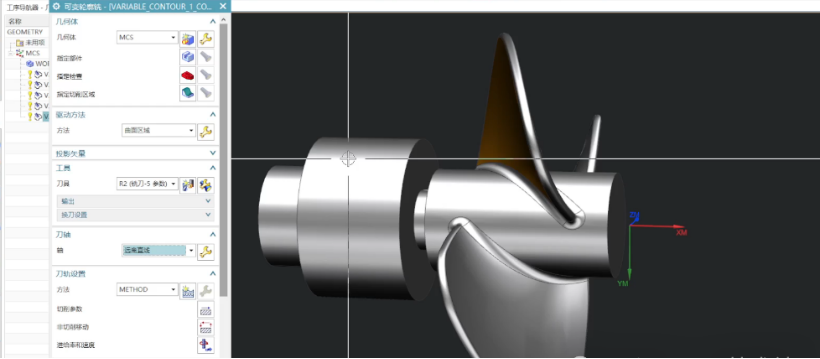
A 17-blade air compressor impeller studied in one of these articles possesses typical structural parameters: blade height at outlet 30 mm, blade height at inlet 65 mm, and minimum clearance between adjacent parts <8 mm, based on high-torsion and variable root fillet designs to enhance aerodynamic performance. We conducted complete-process modeling based on UG software: fitting spline curves to discrete point data, generating blades by free-form surfaces, and combining them with a hub solid. During modeling, curvature of curves analysis and smoothing processing were performed to prevent hidden dangers such as breakpoints and abrupt turns during the subsequent tool path generation. Afterwards, we completed NC process path planning on the UG platform and exported tool position trajectories, a very CAD/CAM integrative process.
Major machining issues incurred due to such configurations are:
- Thin feasible tool posture range with susceptibility to interference is provided by deep cavity, high torsion angle, and narrow channel together;
- Φ6 mm or thinner ball-end mills with poor rigidity and high danger of tool breakage are required for finishing;
- High tendency of free-form surface continuity differences to produce deviations from actual paths to theoretical surfaces;
- Rotation axes of machine tools must simultaneously fulfill accuracy and responsiveness in big posture changes.
- These conflicting factors make interference a priority issue in five-axis machining.
Typical Interference Types in Five-Axis Paths
Path planning for five-axis linkage machining of complex flow channel impellers is faced with massive interference control challenges. Three typical types of interference and their causes are discussed briefly as follows:
Geometric Interference Between Tool and Workpiece
Difficult channel areas of flow contain high curvature transitions, especially at transition zones of the blade roots or hyperbolic connecting sections at leading edge of blade. Physical contact between the tool tip and the workpiece surface tends to occur if path planning does not consider the tool profile and local minimum clearance. Such interference usually happens when ball-end or tapered ball-end mills perform contour cutting close to blade walls, and it is mainly regulated by overall tool corner path matching, surface normal distribution, and tool radius.
Collision Risks Between Tool and Fixture Structure
Because impeller elements typically utilize customer-specific fixtures with asymmetric boundaries, inclined pressure blocks, or ( encircling) module sets, the complex fixture shape easily causes interference during posture changes in paths. Especially during first-piece process debugging or non-optimized clamping structures, the possibility of tool body contact with fixture flanges or corners increases significantly, potentially causing equipment alarms or machining stops in worst-case scenarios.
Potential Interference Between Tool Shank and Blade Area
Overlength tools may generally be utilized for deep cavity machining applications. However, in large-angle cutting methods or areas of sharp curvature transition, where channel space among the blades is insufficient, spacing between blade back and tool shank will be near the smallest tolerance, risk of rubbing at posture transfer. This interference is generally encountered in regions of tip rotation of the blade or highly curved flow paths, with the dangers being closely related to tool total length, shank diameter, and transition path smoothness.
Root Causes of Interference
During five-axis linkage machining of high-complexity flow channel impellers, interference does not occur by chance but is induced by all-around factors on various levels of the system. The reasons for interference are analyzed systematically from three major dimensions: tool structure, posture strategy, and path generation algorithm:
Mismatch in Tool Structure Configuration and Selection
To maximize machining stiffness and reduce vibration, programming prefers tools of larger diameter or traditional shank. However, in free-surface construction with limited space like channel flow impellers, especially in transition sections of blade roots or narrow angles of rotation regions, such devices are highly prone to actual interference by body profile dimension and local passage space differences. In some debugging cases, we found that initial posture planning without careful consideration of tool profile limitations typically led to repeated rework on the tool path and significantly influenced programming productivity and process cycle.
Lack of Posture Control Strategy and Inadequate Parameter Setting
Five-axis posture control of the tool axis is one of the most critical anti-interference measures. But in actual path generation, without the reasonable tool axis rotation constraints (e.g., minimum rotation radius, maximum inclination limit) predetermined, transient interference would inevitably occur at nodes with sudden posture changes. Discontinuous posture changes can also cause abnormal machine tool acceleration/deceleration, affecting profile accuracy and machining safety. Therefore, ensuring continuity and smoothness of posture planning is the essential measure to remove interference probability.
Limitations of CAM Path Generation Algorithms and Simulation Accuracy
In spite of the fact that modern CAM systems perform automatic path generation functionality, with too complex surfaces, micro-clearance regions, or multi-curvature coupling regions, software modules (e.g., older versions of UG NX impeller modules) still face issues of algorithm accuracy insufficiency and geometric analysis deviation. Paths can be conflict-free in theory, but local contact blind spots may occur during actual implementation or high-precision simulation. Especially for several millimeters of blade spacing, low path resolution and simulation granularity can lead to a situation where interference is not detectable at the first stage and difficult to correct later.
Interference Prevention and Path Optimization Strategies
For five-axis linkage machining of complex flow channel impellers, path interference typically results from illogical tool structures, dissonant posture control, and insufficient simulation checks. To actually avoid interference and ensure machining continuity and security, systematic optimization needs to be done from dimensions such as structural design, path planning, simulation checks, and clamping schemes:
Rational Design of Tool Structure
Thin-shank long-neck ball-end milling cutters with typical specifications Φ3–Φ6 mm are recommended in narrow flow channels and root transition areas for meeting tool accessibility and minimum envelope requirements. At the same time, employing tapered shank or stepped tool structures is suggested to enhance deep cavity machining performance by reducing the shank neck diameter with necessary bending stiffness, in fact, reducing collision risks caused by tool shank interference.
Optimization of Posture Control Strategy
In path generation, adequate tool axis inclination limits (recommended to be ±20°) can be set, and posture transition functions with smooth figures (such as Bezier curves or S-shaped figures) should be used to slowly modulate tool axis jumping so as to avoid tool impact against workpieces or fixtures due to sudden angle changes. For interior flow channel areas of complex nature, a segmented posture reconstruction procedure should be adopted, re-setting tool axis orientation in substantial parts (blade roots and connecting arc surfaces) to optimize the incident angle control.
High-Precision Simulation and Interference Verification Mechanism
Embed 3D envelope dynamic calculation algorithms (e.g., the SmartSim module) in the path simulation process to analyze in real-time the minimum tool, tool shank, workpiece, and fixture clearance. Building a full-element collision detection model allows for a “zero-interference” verification and early warning system on the entire path. Based on our experience, this method can pre-warn >95% of the likely interference points in advance, greatly diminishing rework risk in debugging.
Segmented Machining Strategy and Flexible Fixture System
For highly twisted blades or very deep channels for workpieces, a multi-stage path division strategy of “roughing—local pre-machining—finishing” is recommended. High-precision micro-tools + optimized posture strategies are used locally to promote machining quality in difficult-to-access zones. Meanwhile, modular flexible fixture systems (e.g., adjustable multi-axis positioning platforms) are introduced to enhance clamping degrees of freedom and machining windows, enabling each segment of the path to be finished efficiently in the best posture.
Conclusion
Path interference in five-axis machining of complex flow channel impellers is not only a geometric issue but also a multiple integration issue of software algorithms, tool structure, posture control, and machining process. As the frontline engineers, we believe that it can be done only if the geometric precision of CAD modeling, path control capability of CAM systems, and interference prediction functionality of simulation systems are coordinated with each other. Only by doing so can high-quality impeller manufacturing be fully achieved.


