

With the rapid pace of aviation, power, and high-tech device industries’ evolution, impellers as the principal moving components are facing ever higher standards for machining accuracy, surface quality, and geometrical consistency. In traditional process streams, disconnection between information, data conversion errors, and feedback latency between design and manufacturing have been the obstacles to meeting high-quality production specifications of complex impeller profiles.
What is CAD/CAM?
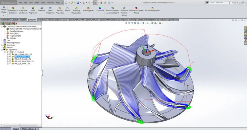
Impellers are typical “hard-to-machine parts” with their extensive change of space curvature, thick but heavy-walled configurations, and complex flow channels. In the traditional model, following geometric modeling by designers using a CAD system, designers need to export files to an individual CAM platform for machinability planning for machining paths. It involves file format transformation problems, loss of structural information, and redundant modeling, significantly weakening design efficiency and machining consistency. The CAD/CAM combined technology brings about a smooth process of impeller manufacture, from digital closed-loop of geometry design to tool path generation, machining simulation, and NC code output, accelerating the development process and improving the accuracy and efficiency of machining.
At the same time, CAD/CAM/CAE software technology as the overall approach to support new manufacturing transformation and upgrading is gradually transforming from traditional 2D drawing and independent modeling systems to integration, collaboration, and wisdom. Foreign integrated platforms such as PTC’s Pro/E, Dassault’s CATIA, and Siemens’ UG NX have been widely used in aviation, automobiles, marine, and other industries, acting as core technical carriers to realize design-manufacturing integration. Especially in the traditional manufacturing process of impellers, involving high precision and complicity, CAD/CAM integrated processes have emerged as a necessary means to guarantee quality and efficiency.
Fine Construction of CAD Models and Extraction of Structural Features
During the CAD modeling stage of impellers, manufacturing viability as well as aerodynamic design requirements must be considered. Using parametric modeling software (e.g., Siemens NX, PTC Creo, CATIA, etc.), full parametric control over blade profiles, flow channel boundaries, and root contours can be maintained. The following should be considered in advance while creating the geometry:
- Machining direction accessibility analysis: Ensuring five-axis tool posture optimization space for the avoidance of blind spots and interference zones.
- Transition fillet and chamfer design: Coordination of flow quality and machining tool path smoothness to improve final surface quality.
- Definition of auxiliary positioning features:E.g., datum holes and clamping surfaces, to be utilized in future clamping and detection for process stability improvement.
These structural information can be directly accessed and called up in the CAD/CAM integrated environment, with complete geometric semantic support for downstream process planning, and significantly reduced probabilities of recurring modeling and data loss.
CAM Path Planning and Strategy Optimization
Based on the accurately constructed CAD model, the CAM system autonomously calculates multi-axis machining strategies from structural properties, machining objectives, and properties of the material. Standard path planning methods are:
Five-Axis Machining Strategies
Five-axis machining is the most important technology in high-precision impeller surface machining. Typical strategies are:
- Z-level contouring: Useful for blade sides and free-form surfaces, ensuring tight tool envelope fit with target surface;
- Flowline strategy: Establishing paths along the direction of the blade profile for maximum tool changes and feed interference;
- Spiral plunge and envelope trajectory: Suitable for complex transition areas of blade roots to achieve stable material removal rates and high surface quality.
Tool Path Optimization and Collision Checking
With combined simulation functionality, end-to-end analysis of tool postures, fixture interference, feed rates, and acceleration/deceleration paths is achievable. Proper ball-end mills, tapered ball cutters, etc., are chosen from the tool library to ensure proper surfacing of detail areas on curved surfaces. With the capability of machining residue analysis, potential uncut areas are identified to enhance final surface integrity.
Collaborative Design of Integrated Process Flows
CAD/CAM integrated collaboration in the manufacture of new impellers has emerged as a significant technique to develop manufacturing efficiency and quality control. Integrated software platforms make digital collaboration from product modeling and process planning, simulation verification right up to machining execution feasible, thereby overcoming information barriers to design and manufacturing and creating an efficient closed loop.
First, with parametric modeling and shared process limitations, the designers can establish pre-defined machining feasibility and restrictions in the early phase, such that structural designs come closer to manufacturing reality. The system automatically detects machining features from the 3D model, such as blade shapes, base hole systems, chamfer zones, etc., and automatically provides corresponding process strategies and tool types.
During the CAM period, there is automatic tool path generation and simulation checking. With material property integration, machine capability integration, and tool integration, the system intelligently allocates cutting paths, identifies potential interference, overcutting, and other errors in advance and smoothes out machining plans via virtual simulation. Generated CNC code can be dispatched directly to the workshop machine tool system, saving programming and preparation cycles and improving resource utilization.
More importantly, post-machining inspection information such as dimension errors and surface roughness can be fed-back to the design side to achieve process closed-loop control. By comparing measured data against design targets, design and manufacturing teams can jointly revise models, optimize tolerance designs and parameter settings, and increasingly implement the intelligent manufacturing idea of “design-to-manufacturing.”
Such integrated closed-loop process significantly enhances the response speed of the process and flexible manufacturing capability and provides a data-based platform for enterprises to deploy digital twin systems and serves as an important supporting road for the transformation of intelligent manufacturing.
Comparison and Application of Mainstream CAD/CAM Systems in Integrated Processes
Currently, well-known CAD/CAM systems in the market, such as CATIA, Pro/E (Creo), UG NX, SolidWorks, and AutoCAD, all have their technical strengths and applicable scenarios respectively:
- CATIA: Developed by Dassault, it has mature surface modeling and system integration functions, commonly used in aerospace OEMs and engine enterprises, especially suitable for complex free-form surface design.
- Pro/E (Creo): PTC’s top seller, aimed at parametric modeling and feature-based design, best suited for high-level component modeling and process-integrated preparation.
- UG NX (Siemens NX): Excels in intricate part modeling and machining, such as aviation impellers, with advanced CAM modules and simulation capabilities, often used for five-axis path optimization.
- SolidWorks: Oriented to SME design work, suitable for rapid prototyping and assembly design, with good compatibility, but not good at complex free-form surfaces and five-axis machining.
- AutoCAD: Mostly 2D design, suitable for engineering drawing and annotation of the structure, being gradually replaced by complex part manufacturing.
UG NX and CATIA are the mainstream software in impeller machining due to their high integration, rich machining strategies, and good surface processing capability.
Application Case Analysis
Certain particular aero-engine titanium alloy impeller uses a UG NX-based integrated design platform to create a parametric model of the blade and to input clamping datum information in the design stage. The CAM module processes five-axis tool paths, and the simulation module performs interference checking and residue calculation. Roughing and finishing are then completed in one clamping on a five-axis machining center. The machining results demonstrate that the blade deviation is controlled in ±5μm, and machining efficiency is increased by 30%, affirming the prominent advantages of CAD/CAM integration technology in high-precision processing.
Conclusion
CAD/CAM integrated impeller machining process design ensures unified integration from design intention to machining implementation, removing problems such as information scattering, path redundancy, and quality variation in traditional processes. It is the mainstream tendency of next-generation high-end complex component manufacturing. With the large-scale application of digital twin, smart manufacturing, and AI-process planning, higher-level process intelligence, data closed-loop, and manufacturing autonomous optimization will be achieved in the future, and ensuring good technical guarantees for high-performance impeller manufacturing and providing historical opportunities for independent development of Chinese manufacturing software.


