
With precision machining demanded by high-end manufacturing, especially the aerospace and energy sectors, on a larger scale, traditional manual tool setting processes are increasingly reflecting bottlenecks in efficiency, accuracy, and data management. Impellers are typical high-precision free-form surface components that attach much importance to the precision and stability of tool parameters; even tiny changes can produce contour errors or overruns of blade thickness. This paper therefore explains the comprehensive design and application value of automatic tool setters for CNC machining of impellers systematically.
Introduction
CNC five-axis machining centers are the predominant machines used in the manufacture of complex components such as titanium alloy impellers in aero-engine manufacturing. But five-axis free-form surface machining is very sensitive to tool length, diameter, and wear state. As a veteran engineer with dozens of years of high-precision five-axis programming and machine tool integration expertise, I well understand that traditional manual tool setting not only consumes a long period but also depends heavily on technical personnel, with numerous sources of error, incapable of meeting the requirements of small-batch, multi-type, and high-consistency impeller production.
In recent years, automatic tool setters have become more and more a key module in the intelligent upgrading of CNC machining centers as a necessary measurement part for on-line tool detection and real-time parameter compensation. By implementing them in machining, they can automatically calibrate tool radius and length as well as perform broken tool detection and wear trend analysis using G31 skip commands, significantly improving the machining reliability, efficiency, and production consistency of complicated impellers.
Tool Errors and Detection Requirements in Impeller Machining
Titanium alloy impellers, being major high-precision components of an aero-engine, the machining quality of which has a direct impact on the performance and service life of the entire engine. In practice, due to the complex geometric composition and very minute manufacturing tolerances of an impeller, the precision control and condition monitoring of the milling tool are over-demanded. Even minor tool parameter deviations will cause machining dimensional overruns or even scrapping of the whole part. Therefore, finding and addressing tool error management issues has become a critical link of the impeller machining quality control system.
High Error Sensitivity and High Risk of Geometric Mismatch
During the manufacturing of impellers, especially those for high-end aviation-grade products, thickness tolerances for blades are usually controlled very finely at ±0.015 mm, and some top-of-the-line models actually require ultra-precision levels of ±0.005 mm. Under these tight tolerances, a tool length deviation of only a few tens of microns can cause ball-end mill machining tool position height errors that lead to such critical problems as improper cutting of the blade profiles, root interference, or local under-machining. Particularly in free-form surface machining, due to the drastic variation of surface normal direction, local tool position errors will increase non-linearly, making it extremely difficult to ensure machining quality. In addition, cumulative geometric errors may pose a cumulative effect on subsequent dynamic balance, fatigue life, and assembly clearance, leading to risks in product quality down the line.
Wide Variety of Tools and Difficulties in Controlling Tool Change Precision
Impeller machining typically involves a number of operations: roughing, semi-finishing, finishing, and trimming of roots, each having relatively distinct tool types and dimensions. Standard tools are long-shank ball-end mills, tapered forming tools, miniature arc tools, and custom-made special tools for high-precision trimming, and dozens of tools which can be applied consecutively when machining. Traditional manual tool setting not only wastes time and is inefficient but also prone to human setting error or failure during the process of frequent tool change, leading to deviations in the overall machining track. In addition, in multi-axis linkage machining systems, even slight errors in attitude can lead to spatial position deviations of the tool tip, which pose severe challenges to final precision control. Therefore, tool change automation and standardization of tool setting information have become an unavoidable key issue in precision machining.
Long Machining Cycles and Difficulty in Early Warning of Tool Breakage Risks
Due to the high hardness of titanium alloy materials and intense machining heat, the machining cycle for single-piece machining of integral impellers generally ranges from 8 to 12 hours. During such long uninterrupted cutting processes, if tools are damaged with defects of breakage, chipping, or thermal fatigue cracks that go unnoticed in time, the machined impeller will need to be scrapped off completely, resulting in 成倍 loss of time and material. Most importantly, when there is not an on-line tool breakage detection device available, the system will continue along the initial trajectory, not only damaging the workpiece, but also most likely creating equipment failure conditions such as abnormal spindle load or mechanical crashes. Therefore, the development of an on-line tool breakage detection mechanism is a necessary measure to ensure the reliability and economy of continuous machining.
High Requirements for Multi-Batch Consistency and Traceability
In the process of aerospace production, process traceability, process stability, and first-last piece consistency are essential measuring factors of production quality control ability. Manual tool setting for multi-batch alternating production is susceptible to tool data parameter drift due to variations among people, operation errors, or lost records, resulting in geometric differences within the same type of impellers across different batches and affecting product consistency. Besides, unretrievable information holds back post-mortem quality checking and responsibility tracing. Therefore, basing an equipment-based auto tool setting system and digital tool library can not only standardize and integrate tool setting parameters, but also, through integration with MES systems, achieve full-process digital traceability and anomaly logging.
Functional and Structural Composition of Automatic Tool Setter Systems
Automatic tool setting systems consist of two core components: hardware and control software, whose design must meet three requirements: high precision, high integration, and real-time linkage.
Functional Modules
| Module Name | Function Description |
| Tool Length Detection | Precisely measures Z-axis length differences and automatically generates H-value compensation |
| Tool Radius Detection | Measures tool diameter, especially suitable for ball-end mills and bull-nose mills, facilitating contour compensation |
| Tool Wear Monitoring | Collects trends of multiple measurement data to determine wear level and automatically prompts for tool replacement |
| Tool Breakage Alarm | Automatically stops and alarms when no tool is detected or when length jumps occur, avoiding further incorrect machining |
| Data Writing and Feedback Mechanism | Automatically writes detection results to system macro variables and tool offset tables, reducing human intervention and improving consistency |
Hardware Composition
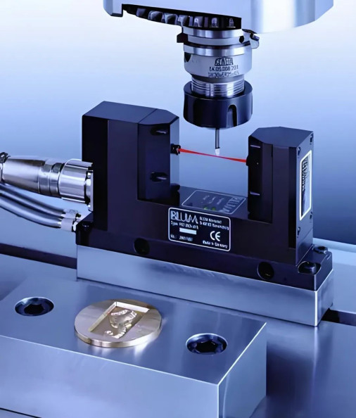
- Measurement Probe: Two types: contact (electrical contact) and non-contact (laser). Laser types (e.g., BLUM TC64) are capable of tool rotation-free high-speed detection, which is applicable in high-precision machining centers;
- Mounting Structure: Often uses a T-slot embedded base, equipped with a pneumatic chip guard and elastic limiting mechanism to ensure measurement accuracy and environmental adaptability;
- Signal Module and PLC: Trigger signals are connected to the FANUC system via I/O ports, connecting skip commands (G31) to perform tool breakage response.
Integrated Design Strategies and System Linkage Implementation
In realization of a smooth and consistent tool setting process, threefold full-system optimized design is necessary in physical integration position, electrical interface, and program logic.
Installation Structure Optimization
After testing on various machine models, we concluded that installing the tool setter at the spindle tool change path corner, together with a magnetic quick-mount base, will eliminate cutting interference and facilitate maintenance. For machining centers with two tables, there can be independent tool setting units per station to support parallel tool setting operations.
FANUC System Program Interface
In the FANUC system, the custom tool setting programs such as O9023 or O9002 can be called using G65 macro commands, in addition to G31 high-speed skip signals for precise detection:
gcode
G65 P9023 H5. // Perform automatic tool setting for tool 5 G65 P9023 H6. W0.05 // Perform tool breakage detection for tool 6, tolerance ±0.05mm
During the occurrence of the G31 skip command, the system stores the coordinates of the measurement point in variables (for example, #5063 in the case of Z-axis), calculates the difference between the reference tool and the actual tool using macro variables, and stores it in the H table to enable automatic compensation.
Full-Process Automation
The tool setting process is as follows:
plaintext
Program start → Read tool number → Call tool measurement subprogram → Tool setter starts detection
→ Measurement result feedback → Write to compensation table → Determine wear/breakage
→ Decide whether to continue machining → Update database/alarm and stop
This process can also be integrated with MES systems to upload and statistically process tool setting data automatically, thus enabling the prediction of tool life and workshop maintenance reminders.
Application Case Analysis
Aerospace production company uses FANUC five-axis machining centers to cut large titanium alloy impellers with frequent change of product, long single-piece machining time, and very rigorous requirements for machining accuracy and consistency. Manual tool setting was used as the original process, which required issues of low efficiency and error drift.
Solution
A BLUM laser automatic tool setting system was installed, with a support O9023 tool measurement macro program developed. Coupled with a data writing module, tool offsets and tool breakage status are automatically stored, entirely removing manual tool measurement.
Effect Comparison
| Project Indicator | Manual Tool Setting | Automatic Tool Setter Integration Scheme |
| Average Tool Setting Time per Tool | 3.5 minutes | 18 seconds |
| Tool Length Error Control | ±0.03 mm | ±0.005 mm |
| First-Piece Qualification Rate | 89% | 98.7% |
| Machining Consistency Deviation Range | ±0.022 mm | ±0.011 mm |
The above figures fully validate the excellent advantages of automatic tool setters on improving CNC impeller machining efficiency and quality.
Conclusion
Based on this study and engineering verification, we can clearly recognize that automatic tool setters as indispensable “precision eyes” in CNC impeller machining, their overall design quality will directly affect the intelligence level and production rhythm stability of the entire machining system. Through the systematic ordering of measurement units, macro programming in a compact way, and firm integration of standardized data writing techniques with control systems, closed-loop control of tool setting data at the complete process level can be achieved. In future manufacturing environments with higher requirements, tool setters will not be auxiliary stations but become core nodes combining sensing, analysis, and feedback within CNC systems.


