
Being crucial rotating components in aerospace, energy, and high-performance equipment industry, contour accuracy of impellers directly affects the performance, stability, and energy efficiency of the entire machine. Traditional contact techniques fall short in measuring complex free-form surfaces, limited by limited measuring points, long cycles, and surface contact errors. Recent years have seen non-contact laser scanning technology gain widespread application in impeller contour error analysis based on its high resolution, efficiency, and non-invasiveness.
Introduction: Necessity of High-Precision Impeller Contour Error Detection
Because impeller blade contours directly govern aerodynamic performance, efficiency of energy conversion, and system dynamic stability as the basic characteristics of turbomachinery, quality of contours directly influences machine’s operational performance. Deviation of contours from tolerance limits will lead to more secondary flow losses, inconsistency of vorticity fields, local stress concentration, or even prevent premature failure of the entire machine. Effective and precise monitoring of impeller geometric quality, especially contour errors, therefore, turned into an inevitable part of product quality assurance in production.
Despite this, conventional contact devices like Coordinate Measuring Machines (CMMs) have serious handicaps for impellers with complex curvatures, sharp edges, and narrow-wall structures: limited measuring points, low efficiency, and risk of micro-damage by probe contact. Laser scanning technology, particularly non-contact triangulation-based instruments, achieves million-level point cloud capture by rapidly scanning the whole impeller surface with high precision. This speeds up quality inspection from “backend to frontend,” enabling digital closed-loop manufacturing quality control.
Working Principle and Measurement Advantages of Non-Contact Laser Scanning Technology
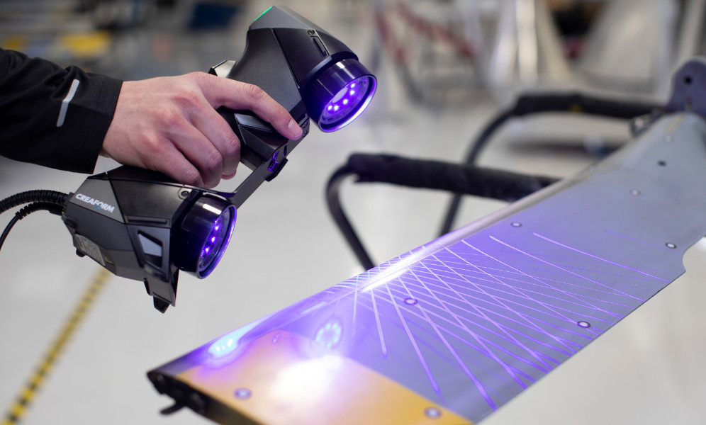
Non-contact laser scanning technology primarily projects laser beams onto the surface of the workpiece and uses time-of-flight (TOF), phase shift, or the principle of triangulation of reflected light to obtain 3D spatial coordinate information of the measured object and produce high-density point clouds. Widely used devices such as laser line scanners or structured light sensors have excellent advantages:
- High sampling density and full-surface coverage: Scanning million-level point clouds in one go, no “missing measurements” like in traditional methods, ideal for complex free-form surfaces.
- High-speed measurement and automation: Scanning cycles are minimized to minutes in normal applications, allowing automated measurement processes to respond to industrial site tempo requirements.
- Non-contact and non-destructive: Ideal for thin-wall and curved blade structures, avoiding surface indentation and probe compensation errors from contact.
- Adaptability to complex surface topography: Multi-angle scanning and adaptive path planning ensure (blind spot)-free data capture, which accurately reconstructs difficult-to-access areas like rims and blade crowns.
In my practice project, as compared with traditional contact quality inspection methods, the incorporation of laser scanning not only reduced measurement cycle duration from 40 minutes to 12 minutes but, more significantly, improved contour error data spatial integrity and visual intuitiveness, significantly enhancing front-end process feedback efficiency and manufacturing closed-loop optimization.
Point Cloud Processing and Error Analysis Process: The Key Chain from Acquisition to Evaluation
Data Preprocessing and Registration
Laser scanning point cloud raw data must be subjected to a series of preprocessing steps:
- Filtering and denoising: Remove outliers due to reflection interference, material surface texture, or external noise.
- Coordinate registration: Register scan data with CAD models with high precision by applying Iterative Closest Point (ICP) algorithms or reference feature matching. Finally,.
- Mesh reconstruction and surface fitting: Convert discrete point clouds to continuous surfaces or polygon meshes, which serve as the basis for error visualization and numerical analysis.
Error Evaluation Methods
Error analysis typically employs the point-to-surface shortest distance method, taking into account each point cloud point’s normal offset from the CAD model as error data, supplemented by:
- Color heat maps: Visualize deviation distribution to assist with rapid defect area (positioning).
- Numerical statistical indicators: Maximum deviation, mean absolute deviation, RMS deviation, etc., to convey the total level of deviations.
- Section feature analysis: Obtain geometric properties such as profile accuracy, bend, and twist from individual blade sections to aid in the topography analysis.
Accuracy Analysis: Influencing Factors and Engineering Practice Feedback
Its usage in the measurement of complex impeller geometry relies on a number of factors to achieve maximum accuracy. Combining engineering methods, this paper critically examines the influencing factors of measurement precision from four key perspectives—system performance, scanning techniques, workpiece surface conditions, and data processing—and provides technical assistance and optimization suggestions for engineering practice.
Equipment Parameters and System Resolution
The basic hardware of laser scanning devices determines the accuracy limit. For instance, in a particular four-coordinate laser scanning system, its measurement precision is less than 2μm, and the point sampling rate is up to the million level; using high-precision grating rules and advanced servo systems, it can accurately reconstruct the intricate surface topography of the impeller.
In addition, the beam focus diameter, sensor sampling rate, and the light system stability directly affect the resolution and accuracy of the point cloud. The smaller the beam focus, the more dense the details achievable; the larger the sampling rate, the denser the data and the more complete the measurement results. Its anti-vibration structure and thermal regulation are also the key to ensuring the consistency of repeated measurements.
Scanning Path and Strategy
Reasonable scanning path planning is necessary to avoid omission of data and blind spots of measurement. The impeller is a complex surface with many depressions and curved surfaces. Single-angle scanning will suffer shadow occlusion and dead corners and thus cause missing data in critical regions.
With multi-angle and multi-posture scanning methods, and path planning algorithms for optimization of scanning trajectory, point cloud coverage rate is maximized and measurement blind spots are avoided. For critical components such as blade crowns and airframe surfaces, scanning distance and angle are prioritized to design for complete data and lay the foundation for subsequent analysis.
Surface Material and Reflective Interference
Materials for impellers are usually high-gloss metals or black-colored alloys, and the reflection properties of the surface are complex, prone to (susceptible) causing laser signal scattering or deflection, causing point cloud quality to degrade.
For reflective surfaces that have high reflectivity, matting powder can be sprayed or the power of laser emission and exposure time optimized for increasing the intensity of laser echoes and point cloud uniformity. This processing effectively reduces noise and improves the accuracy in capturing details and edges, hence improving the general measurement data reliability.
Data Registration and Error Fitting Algorithm
The CAD model and the point cloud precise registration forms the core of the error analysis. The registration algorithms like ICP (Iterative Closest Point), K-D tree nearest neighbor match, and surface fitting techniques in the context of the minimum zone method are used generally.
These algorithms optimize increasingly the space match between model and point cloud to minimize registration errors. Coupled with cross-sectional feature extraction and geometric parameter checking (e.g., profile accuracy, bend, twist), it can accurately reflect on the impeller topography deviation and act as a scientific basis for process adjustment of manufacturing.
Analysis of Practical Cases: Measurement of Blade Profile, Bend, and Twist
In the aero-engine blade measurement experiment, a high-speed compressor impeller was used for the non-contact scanning measurement by a four-coordinate laser measurement platform to implement a systematic test of contour errors:
Cross-Section Profile Error Analysis
The mean deviation of the point cloud and design model at each common section was achieved by the K-D tree algorithm. It was shown from the results that the profile error distribution was stable, and most sections’ deviation was below ±0.02mm, meeting the requirements of precision machining.
Bending Deformation Error Analysis
By using the distance from the middle part centroid point to the line linking the end part centroid point, the overall general bending error was within ±0.01mm, which presents good overall surface consistency.
Twist Error Analysis
Through the detection of the twist deformation angle with end point angle difference, the maximum angle difference was less than 0.2°, which fully illustrated the sensitivity and stability of laser scanning technology indetecting (small) angle change.
In addition, the comparison with the CMM results shows:
| Measurement Index | CMM Result (mm) | Laser Scanning Result (mm) | Difference (mm) |
| Maximum Deviation | ±0.025 | ±0.028 | 0.003 |
| Average Error | 0.011 | 0.012 | 0.001 |
| RMS Error | 0.009 | 0.010 | 0.001 |
Precision is indeed the same, and efficiency is significantly improved, thus proving that laser scanning fully owns the potential to replace or supplement CMM in industrial practices.
Summary
Non-contact measurement-based laser scanning technology has proved to be an efficient tool for contour error analysis of impellers by virtue of high resolution, non-contact, and high efficiency. Its accuracy is jointly determined by the performance of equipment, scanning strategies, and data processing levels. With the advancement of laser sensor technology and intelligent algorithms, this technology will be used more extensively in quality inspection of impeller manufacturing in the future, including online real-time testing and intelligent defect recognition, promoting the smart and digital development of impeller manufacturing.


