
Impellers are key power transmission members in industrial machines such as pumps, fans, and turbomachinery, and their performance directly affects the efficiency, stability, and long-time working capability of the entire machine. Aiming at the specific needs and application conditions of different customers, tailor-made impeller designing and testing must be strictly subject to a serious matching procedure so that the final-delivered products not only meet design specifications but also match the actual application context.
Introduction
Being one of the key components in rotating machinery, impellers have widespread applications in equipment such as pumps, fans, and turbines. Their major function is to effectively transfer energy to the fluid by converting mechanical energy and hydrodynamic characteristics, driving fluid flow. Therefore, impeller design must not only consider basic parameters such as flow rate, head, and rotational speed but also comprehensively incorporate medium properties, operating temperature, material strength, and other factors. According to customers’ special demands and equipment working conditions, custom-built impellers not only can obtain maximum equipment working efficiency but also significantly extend equipment service life and reduce maintenance expenses.
As an engineer with extensive experience in equipment customization and optimization services, I firmly believe that precise performance parameter matching and strict testing processes are the key to ensuring the quality of custom-made impellers. Precisely for this reason, performance tests and parameter matching of impellers not only are vital steps in design and manufacturing but also guarantees for customers to obtain reliable and efficient equipment.
Performance Parameter Matching Process for Customer-Customized Impellers
Customized impeller design and production for customers is a highly individualized and high-tech process, with in-depth knowledge of the customers’ actual working conditions. The combination of mature design experience, advanced analysis software, and standard parameter matching process can provide customers with superior performance, extended service life, and favorable economy of customized impeller products. In the process, a complete and standard parameter matching process is the most important link to ensure the design direction and goal correctness.
Requirement Collection and Analysis
Impeller design should not be started until customer requirements are understood fully and deeply. This phase is the basis of the whole customization process. The design team must gather in detail all types of requirements for impellers from customers, particularly key parameters like flow rate, head, pressure, rotation speed, efficiency, and medium properties. By multiple interactions with customers, determine their usage conditions and working conditions requirements, including special requirements such as environmental temperature, medium category, and medium concentration. From this information, the design team can accurately lock in the direction to ensure the correctness of the next design direction.
For example, in a project cooperated with a petrochemical enterprise, the customer needed to custom-make a high-efficiency and corrosion-resistant centrifugal impeller. Through close contact with the customer, we learned that the special medium type was high-concentration brine and the working environment temperature was high. Therefore, considering corrosion resistance and strength, we selected titanium alloy materials in material selection and designed the medium’s flow characteristics to optimize the performance.
Parameter Calculation and Type Selection Design
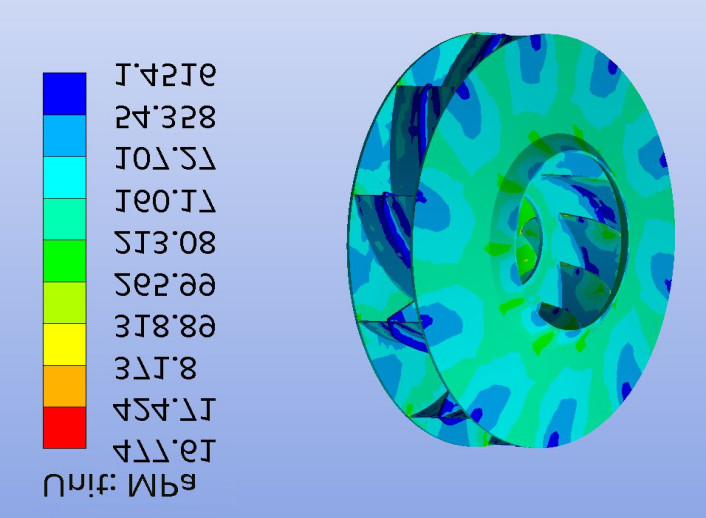
After determining the requirements, the initial design of the impeller is done based on the principles of fluid dynamics. Assisted by numerical simulation (e.g., CFD) and engineering experience, the design team selects and optimizes the key performance parameters of the impeller, e.g., the specific speed, shaft power, efficiency curve, etc. During this stage, we not only consider the performance of a single impeller but also need to ensure the impeller is able to perform the best role under actual working conditions by simulating the flow field change with different working conditions.
Through Computational Fluid Dynamics (CFD) simulation, it is possible to optimize and tune parameters such as the geometric shape, blade angle, and flow channel curvature of the impeller to minimize hydraulic loss and vortex formation. For example, when designing a fan impeller, we found through CFD simulation that the flow channel shape in the original design had visible backflow that affected efficiency. Therefore, we optimized the flow channel angle for improved overall efficiency.
Performance Optimization and Scheme Confirmation
Based on the preliminary ideas of the design, the design team will further optimize the shape of the impeller and flow channel to reduce hydraulic loss and improve performance and stability. Optimization generally entails repetitive debugging of the impeller inlet edge, outlet angle, number of blades, and curvature in order to obtain their optimum hydrodynamic characteristics. At this stage, we work together with customers in close collaboration to validate the optimized design scheme to ensure it not only meets the requirements of technical specifications but also satisfies customers’ usage needs.
For example, in a fan project, a client requested that we improve efficiency at a lower rotational speed. By modifying the thickness and angle of the impeller blades, we made them more compliant with the operation requirements in a low-flow velocity situation, thereby significantly improving the overall efficiency of the system.
Impeller Performance Testing Process and Specifications
Impeller performance testing is the most vital link to ensure the product performance to meet standards and quality to be reliable before delivery. A standardized, complete, and detailed testing procedure can not only fully reflect the level of design and manufacture of the impeller but also provide users with quantifiable and traceable performance basis. The testing process includes the entire process of pre-delivery inspection, test preparation, data measurement, and analysis to ensure that all the performance parameters meet design and specification requirements.
Processing and Assembly Inspection
After the impeller design is completed, it goes into the processing stage, and the manufacturer will carry out complicated processing according to the design drawings. Following processing, the outer dimensions, structural precision, and dynamic balance of the impeller should be rigorously inspected as per design specifications. To guarantee the stability and safety of the impeller during real work, strict dynamic balance adjustment should be performed to prevent equipment vibration and damage due to imbalance.
In real operations, I have participated in the after-processing inspection of impellers numerous times, found some minor errors in the processing process, and made adjustments in time to avoid future performance problems. For example, in processing a fan impeller, after dynamic balance tests, we found that the impeller had a slight vibration problem at high rotational speeds, and after fine tuning, we finally ensured its stable operation.
Preparation of Performance Testing Platform
In the test preparation phase, it is first necessary to build a test platform that meets standards and ensure the accuracy and reliability of test equipment. Generally, the test platform needs to be established according to ISO or GB/T standards, with precise equipment such as flowmeters, pressure gauges, power meters, tachometers, etc., and calibrated in advance. Apart from that, to ensure the accuracy of the test results, the test platform’s environmental conditions should also be controlled within normal. Such as temperature, humidity, etc.
Flow Rate and Head Measurement
Flow rate and head measurement is done first during the test. During operation of the impeller, we ought to measure point by point the flow rate, head, and power of the pump at the inlet and outlet and plot performance curves such as Q-H, Q-P, Q-η and their deviations from design targets. The ultimate goal of this stage is to ensure that the impeller has the ability to supply power efficiently and stably in varying operating conditions.
Vibration and Noise Inspection
The stability of the impeller’s operation is not only reflected in the performance of flow rate and head, but it also needs to take vibration and noise into consideration. At each operating condition point, we need to monitor vibration and noise data to ensure that there is no abnormal vibration or noise problem in the operation of the bearing housing and the entire equipment at various load conditions.
Data Analysis and Test Conclusion
After the test is completed, all the data will be analyzed comprehensively. By comparing the deviations of parameters such as flow rate, head, power, efficiency, etc. with the design values, analyze whether their performance meets the expected goals, and prepare a detailed test report. The report will be an important foundation for customers to decide whether the product quality and performance are qualified.
Conclusion
The customer-customized impeller performance parameter matching and test is the most important link to ensure the impeller can exert its proper function in actual application. From requirement analysis to optimization design, through to the final test, strict procedure and scientific test methodology can help to achieve the maximal quality and reliability of the impeller. In a number of projects that I have participated in, this process has not only facilitated the delivery of products on time but also provided customers with more competitive services.


