
In the high-end manufacturing, impellers, as the typical representative parts of complicated free-form surface parts, have been widely used in the key equipment of aero-engines, gas turbines, and compressors, which imposes extremely high requirements on their surface quality and shape accuracy. With the popularization of five-axis CNC machining technology, the traditional processing method can no longer meet the constantly improving manufacturing accuracy. Tool compensation technique, as one of the basic approaches to master the error between the theoretical trajectory and real cutting path of tools, has increasingly become a crucial guarantee for achieving high-precision impeller machining.
Introduction
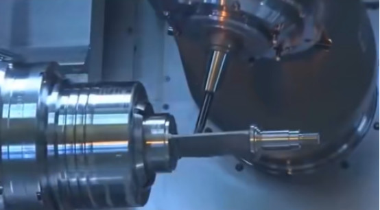
Impellers’ geometry, characterized by their typical 3D free-form surfaces, thin-walled variable-thickness blades, and complex flow channel topologies, makes their manufacturing process far more difficult than that of conventional mechanical parts. In aerospace, energy machinery, and other fields, the surface quality of impellers directly affects the overall efficiency, service life, and stability of the equipment. Even on five-axis linkage capable high-end machine tool platforms, the actual cutting point of the tool always differs to some degree from the programmed trajectory—issues such as tool radius error, trajectory deviation caused by posture change, and wear accumulation can dramatically influence the final machining result.
Through a number of titanium alloy and superalloy impeller machining projects, I deeply realize that the tiny trajectory deviation will cause contour distortion at the trailing edge or leading edge of the blade, even lead to fatigue crack. Therefore, how to precisely control machining trajectory through effective tool compensation has become one of the key technologies to ensure machining quality.
Basic Principles and Classification of Tool Compensation
Tool compensation is one key control technology of CNC machining, which attempts to compensate for the space deviation between the “theoretical tool position” and “actual cutting point” caused by the tool geometric parameter, installation error, actual wear, and dynamic posture change. Especially for high-precision machining of workpieces with complicated surfaces like impellers, precise tool compensation is directly related to workpiece contour precision and surface quality, and is the fundamental guarantee for high-consistency and high-quality batch production.
Tool Radius Compensation (G41/G42)
Tool radius compensation is employed mainly in 2D or 2D projection path machining to move the actual cutting position of the tool sideways. G41 for left tool compensation, G42 for right tool compensation, and the compensation value is determined by the difference between the actual tool radius and the program setting. This type of compensation in impeller machining is often applied in contour milling operations of plane parts such as datum surfaces, mounting surfaces, or support flanges for boundary machining accuracy. The rational application of G41/G42 not only prevents duplicative programming of path strategies but also promotes flexibility and efficiency and is a very common path revision technique in 2D machining.
Tool Length Compensation (G43/G44)
Tool length compensation is used for compensating the cutting depth deviation along the Z-axis direction, with G43 for positive compensation and G44 for negative compensation. This function is ideally suited for roughing-finishing operations in multi-layer machining or fixed-depth feature profiles, such as contour cutting and relief machining in blade creation. The system automatically compensates for the machining path based on the pre-established tool length value (measured using a tool setter, for example), avoiding under cutting or overcutting caused by differences between the actual and nominal tool lengths. It is a basic method for ensuring axial accuracy and surface integrity.
3D Posture Compensation
Five-axis linkage machining involves the tool axis direction continuously changing with surface geometry, so traditional 2D or axial compensation can no longer meet machining accuracy requirements. A 3D posture compensation mechanism must be introduced at this point. Based on the angle between the tool axis and the workpiece surface normal, the technology computes in real time the spatial deviation between the tool tip and the theoretical cutting point and compensates the path dynamically in the vector direction. 3D posture compensation is particularly suited to finishing operations in free-form surface areas such as impeller blades and flow channels, not only ensuring tool path smoothness, but also significantly reducing surface step differences and residual marks, improving finish and geometric accuracy of finished products.
Wear and Thermal Deformation Compensation
During continuous batch machining of impellers, tools have to suffer wear and thermal deformation, which makes dimensional deviations accumulate. To this end, machining centers today are often equipped with on-line measuring systems, such as laser tool setters and trigger probes. These devices can measure tool length and diameter variations, or directly detect workpiece geometric errors, at intervals or in real-time and provide feedback to the control system for automatically compensating the path. This type of compensation not only directly enhances the closed-loop control capability of the machining process but also greatly improves the consistency of batch impellers and the minimization of manual intervention frequency, which is one of the crucial technical means for modern high-end CNC systems to achieve adaptive precision control.
Mechanism of Tool Compensation in Surface Quality Control
Tool compensation technology not only ensures geometric accuracy but also plays a very significant role to improve the surface quality of impellers, which is reflected in the following dimensions:
Reducing Surface Roughness
Tool paths without compensation contain “step jumps” or discontinuous changes, which tend to leave tiny steps or vibration marks on the surface. Especially in high-speed and high-precision cutting, there is a remarkable amplification effect of micro-deviations of the trajectory. Through 3D posture compensation and best position calculation of the tool, tool and workpiece contact can be made continuous and smooth, significantly improving surface finish. As an example, in a titanium alloy closed impeller project that I really did, the surface roughness Ra was 1.3μm without compensation but reduced to 0.58μm with 3D compensation, with mirror-level surface quality.
Improving Contour Precision
Complex blades are extremely intolerant to contour error, usually within ±0.01mm. Radius and length compensation corrections of the tool ensure that the machine tool execution route always tracks the theoretical contour, especially in sharp corner areas such as blade roots or trailing edges. When using the Siemens 840D system, I pay particular attention to binding the D-number compensation value in multi-segment tool switching so as to prevent local contour jumps caused by micro-differences between different tools.
Suppressing Local Overcutting and Interference
In variable-thickness areas or narrow-clearance flow channels, uncompensated tool paths are very prone to local “overcutting,” not only damaging the geometric shape but also potentially initiating premature cracks in fatigue-critical areas. Dynamic posture compensation carried out in conjunction with simulation software (e.g., NX ISV or VERICUT) can precisely predict and avoid these interference areas.
Implementation Differences of Compensation in Different Control Systems
CNC systems differ in their method of tool compensation implementation, and the logical differences therein not only affect program structure but also have a great impact on machining flexibility and safety.
Siemens Style: Tool-Compensation Binding (e.g., T01 M06 D1)
The Siemens system uses D-number compensation binding, with automatic call-up of related compensation data when changing tools, suitable for multi-process high-speed machining applications. Its advantages are small programs and high automatization, but the principle of “activating compensation at safe height” must be strictly followed in program writing to prevent accidental tool collision. In one machine tool debugging, I forgot the axial position when opening the D value, which caused an instantaneous Z-axis sink—fortunately, the problem was discovered in advance through ISV virtual simulation, which excluded the real accident.
Fanuc/Haas Style: Command Separation (e.g., T01 M06; G43 H01)
These systems use G43 to expressly activate compensation, and the H-number addresses the compensation register separately, making programming more stringent and suitable for applications with extremely high precision and safety requirements. The advantage is fine controllability of operations, suitable for path debugging of complicated paths and control of multiple tools. However, the code is relatively cumbersome, requiring a higher degree of understanding on the part of operators. In machining Inconel impellers on a five-axis machine controlled by Fanuc 30i, we adhered to the standard process of “G91 G28 Z0 → T tool change → G43 H compensation,” ensuring the safety of each compensation activation.
Implementation Strategies and Optimization Suggestions
To fully utilize the effectiveness of tool compensation in actual production, I have the following suggestions:
- Reasonable Selection: Prioritize CNC systems supporting 3D compensation functions (such as Siemens 840D, Heidenhain TNC 640) and equip with high-precision on-machine measurement systems;
- Standardized Management: Establish a complete tool library and compensation parameter database to ensure traceability and verification of compensation values;
- Simulation First: Use machining simulation platforms like VERICUT and NX CAM to detect path safety and error distribution after compensation in advance;
- Regional Differentiated Compensation: Adopt targeted strategies for different impeller areas, such as precise compensation for blade tips, transition compensation for roots, and posture pre-control mechanisms for flow channel bottoms;
- Personnel Training and Process Standardization: Strengthen systematic training for operators, unifying machining compensation processes, tool setting strategies, and debugging specifications.
Conclusion
Tool compensation technology is no longer a supporting role of CNC programming but a fundamental key means in complex surface high-precision machining, especially for manufacturing impeller-like parts. With the intelligent manufacturing ideas continuing to deepen, tool compensation will be integrated with digital twins, AI path optimization, and industrial IoT technologies, evolving into an intelligent “perception and control” hub in manufacturing systems. For manufacturing engineers, understanding and masterful usage of tool compensation are not only a technical ability but also a reflection of precision manufacturing philosophy. In the future, it is only through actively sensing and pre-correcting such “invisible errors” that we can truly take the initiative in high-precision manufacturing.


