
Accompanied by the rapid development of high-end manufacturing industries such as aerospace and energy power, free-form surface impellers have been performing key roles in much more advanced equipment due to their complex geometric shapes and high fluid flow efficiency. However, traditional machining processes are troubled by numerous issues such as trajectory errors, tool vibration, and surface quality decline. Surface interpolation algorithms, especially on five-axis CNC machines, have been key technologies to solve the above problems.
Introduction
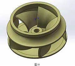
Free-form surface impellers are being increasingly used in aerospace, gas turbines, hydraulic pumps, and other fields, occupying an important position in many high-end equipment with their unique hydrodynamic properties and high efficiency. However, the complex geometry of such impellers, especially their large curvature changes and space twist characteristics, make the traditional machining method, i.e., G1 line segment interpolation, hardly meet machining accuracy requirements. Not only can the traditional interpolation methods produce enormous trajectory deviations, but they also may create problems such as poor surface quality and tool vibration. Because of this, the use of surface interpolation algorithms has been an effective means for removing these problems. Surface interpolation method can significantly improve machining accuracy and efficiency by creating toolpaths directly on mathematical surface models (e.g., NURBS), with very good application potential in five-axis linkage machining.
Interpolation Challenges in Free-Form Surface Impeller Machining
Free-form surface impeller machining is faced with some technical problems, mainly including:
- Severe curvature changes: Traditional interpolation methods (e.g., linear segment interpolation) cannot handle surfaces with large curvature variation, which will lead to trajectory deviation from the target surface and generate large machining errors.
- Lengthy machining trajectories: Traditional G-code typically includes many microscopic segments, which not only increases the amount of calculation but also imposes an incredible burden on the machine tool’s computing resource and control system, affecting machining performance.
- Difficult tool posture adjustment: Tool postures have to be continually adjusted with the surface in five-axis machining; otherwise, machining instability or interference will occur.
- Surface quality issues: The traditional interpolation method may result in a poor machined surface quality due to path breaks and vibration, affecting the flow performance of impellers.
Aimed at these problems, surface interpolation technology has increasingly become one of the most important technologies for solving high-precision and high-efficiency impeller machining in five-axis linkage machining.
Basic Principles of Surface Interpolation Algorithms
The gist of surface interpolation technology is to employ parameterized mathematical surface models (such as NURBS) to create continuous tool trajectories directly within the parameter space. In this way, the algorithm allows the tool trajectories to approximate the desired surface in machining with zero discretization errors and breakpoints inherent to traditional interpolation methods.
The basic principles of surface interpolation algorithms can be summarized as follows:
- Using NURBS surface models: Parameterized surface models are used to avoid discretization error in the conventional approach. NURBS (Non-Uniform Rational B-Splines), as a widely used free-form surface modeling tool in industry, possesses the capability to depict complex surface geometries effectively.
- Trajectory continuity: Surface interpolation methods ensure C2 continuity of toolpaths, which makes tool movement continuous and smooth, thereby reducing vibration and interference in machining.
- of tool positions and postures: In five-axis machining, surface interpolation algorithms adjust both tool positions and postures to ensure continuity and consistency between the tool and the surface.
- Variable step control: The interpolation step is varied based on local curvature variation of the surface, providing fine path control in regions of high curvature.
This interpolation method not only significantly reduces the number of G-codes and improves the response speed of the system but also effectively reduces path errors and tool interference.
Implementation Methods of Surface Interpolation in Free-Form Surface Impeller Machining
The complicated geometric characteristics of free-form surface impellers destined that their machining paths cannot be established on the basis of traditional linear or circular interpolation methods. To achieve high-precision and high-efficiency CNC machining, modern CAM and CNC systems have increasingly adopted surface-information-based interpolation methods, especially key technologies such as Non-Uniform Rational B-Spline (NURBS) interpolation, hyperbolic approximation interpolation, and five-axis tool posture separate interpolation. Some prevalent implementation methods are presented and compared hereinafter:
Accurate Interpolation Strategy Based on NURBS Surface
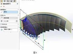
In free-form surface impeller machining, Non-Uniform Rational B-Spline (NURBS) surfaces are widely used to describe complex geometries and are one of the basic forms of current CNC interpolation technology. Impeller surfaces are usually composed of a number of highly continuous free-form surfaces, which not only have non-linearly changing curvatures but also multi-directional twists in space, so that high-precision machining is extremely difficult for traditional three-axis linear interpolation. NURBS surfaces can depict complex surface contours through the parameter space (u-v), thereby creating continuous and smooth tool trajectories within the CAM system. Its basic process is: initially importing the CAD model with NURBS data into the CAM system (such as NX CAM, PowerMILL, HyperMILL, etc.) for guaranteeing the integrity of surface data; then creating equidistant or streamline trajectories in the parameter space for keeping the tool always in contact with the blade surface at an optimal angle; and finally transforming the toolpath data into the machine coordinate system through coordinate transformation and outputting the corresponding G-code. Together with advanced CNC systems (e.g., Siemens 840D sl, Heidenhain iTNC 640) which support NURBS interpolation orders, real-time breakpoint-free interpolation control can be achieved, significantly improving surface quality, contour accuracy, and machining stability. It is the cutting-edge technical means for aviation and high-performance compressor impeller finishing.
Application of Hyperbolic Approximation Interpolation in Non-Standard Surface Machining
Although NURBS surface interpolation is superior in terms of accuracy and smoothness, in some engineering applications, such as STL models obtained by reverse engineering, CAD surfaces with topological defects, or small CAM systems with limited resources, it may be impossible to call upon complete NURBS data for trajectory driving directly. In these cases, hyperbolic approximation interpolation is a good backup strategy. This method generates intermediate tool trajectories between two adjacent contour or flow guide curves on the impeller surface through spline interpolation or Bezier curve fitting, layer by layer near the target surface. Fundamentally, this method is a path approximation reconstruction technology that doesn’t require whole surface parameter expressions to construct interpolation paths with good continuity and machining controllability. Its advantages are low requirements for model geometric continuity, low usage of computational resources, suitability for machining the middle region of blades or non-critical surfaces, and good adaptability to engineering problems such as local defects and rough grid modeling. To machine complex parts with slightly lower tolerance requirements, e.g., guide vanes of turbines and low-pressure pump wheels, hyperbolic approximation interpolation can be an effective engineering addition to enhance general machining flexibility and robustness.
Separate Interpolation Control Technology for Tool Trajectory and Posture
During five-axis machining of free-form surface impellers, the tool is not only required to move on the path but also to adjust its attitude in real time in order to ensure the continuity of cutting angle and tool avoidance conditions. This requires adopting the strategy of “Tool Center Point (TCP) and posture separate interpolation,” which realizes synchronous decoupling control of position and attitude by using high-accuracy interpolation algorithms. The principle is to separately control the tool tip path and tool axis direction during the calculation of the path, using the five-axis CNC system’s multi-channel coordination function to interpolate XYZ positions and ABC or RT rotation angles independently. At the control level, the latest CNC systems (e.g., FANUC 30i, Siemens 840D) can recognize and preprocess the posture change requirements in high-speed machining through Look Ahead preprocessing and high-speed posture compensation functions, avoiding tool jitter, abrupt posture switching, or machining errors caused by insufficient linkage. In addition, in the CAM post-processing chain, Post Builder tools need to be used to carefully debug five-axis interpolation commands to achieve tool axis posture continuous controllability. Such an interpolation method has particular suitability for high-dynamic five-axis linkage machining applications, such as aerospace compressor impellers and gas turbine nozzles with extreme surface variation. Its capacity to regulate posture directly affects the machining efficiency and surface quality of finished products and is among the primary technologies for high-end five-axis applications.
Integration and Development Trends of Interpolation Strategies in Practical Engineering
In tandem with the ongoing development of five-axis CNC technology, surface interpolation strategies are also heading towards higher intelligence and automation. For practical engineering, machining paths cannot always be fully resolved by a single interpolation method, and comprehensive consideration of model complexity, CAM software function, CNC system capability, and practical experience in machining is required. Today, a common practice is to build compound interpolation paths by more than one method: embracing NURBS-based paths for areas of fine geometric quality; employing hyperbolic interpolation compensation in model defect areas; and incorporating tool posture independent control in key machining surfaces for achieving full-process machining quality control. In addition, virtual verification and path simulation (e.g., VERICUT, NC Simul, etc.) have also been the indispensable supporting tools, which conduct a few rounds of collision check, overcut check, and optimization iteration after tool trajectory generation to ensure the safety and efficiency of the generated path. In the future, with the continuous integration of AI-assisted CAM programming, adaptive interpolation algorithm, and semantic-based modeling technology, surface interpolation of complex impellers will no longer be limited to manual strategy setting but move towards an intelligent trajectory generation era of “model-driven path” and “geometry-driven manufacturing.”
Industrial Application Cases and Effect Comparison
In a test of machining an aviation-level free-form surface titanium alloy impeller, conventional G1 line segment interpolation and NURBS-based surface interpolation were compared. The test results were as follows:
| Comparison Item | G1 Interpolation | Surface Interpolation (NURBS) |
| Surface Roughness | Ra 0.8 μm | Ra 0.35 μm |
| Number of G-codes | Approximately 65,000 | Approximately 2,800 |
| Machining Time | 3 hours 42 minutes | 3 hours 05 minutes |
| Maximum Tool Posture Abrupt Change | Over 15 degrees | Less than 5 degrees |
| Vibration and Noise | Significantly high | Stable and low vibration |
The experimental data shows that surface interpolation technology has excellent advantages in machining quality, machining time saving, and tool vibration reducing and is particularly suitable for high-requirement free-form surface impeller machining.
Faced Challenges and Development Trends
Although there are significant developments in surface interpolation technology, in actual application there are still some challenges facing it:
- CNC system compatibility issues: Some old CNC systems may not support high-order interpolation commands.
- CAM system support issues: Not all CAM systems can provide NURBS interpolation functions or interfaces.
- Requirements for real-time computing power: Five-axis linkage machining requires CNC systems to have high computing power to process interpolation trajectories of complex surfaces in real time.
In the future, with the development of industrial CNC systems towards openness and high performance, surface interpolation technology will be combined with artificial intelligence, adaptive control, digital twin, and other technologies to promote the intelligent and automated process of free-form surface impeller machining.
Conclusion
As one of the core technologies of free-form part machining, surface interpolation algorithms have extensive prospects in improving machining accuracy, optimizing machining efficiency, and enhancing surface quality. Free-form surface impeller machining not only can overcome the shortcomings of traditional interpolation methods in the above-mentioned three aspects of spatial continuity, interference control, and surface quality, but also can achieve five-axis linkage machining accurate control by matching with high-performance CNC systems. In the future, with the ongoing development of technology, surface interpolation will play a significant role in more advanced manufacturing industries, leading precision machining technology to a smarter and more efficient stage.


