
Spiral surface impellers are widely used in aviation, marine, energy, and chemical industries and hold a very crucial position in fluid transportation and performance enhancement. However, their complex geometric shapes and structural properties present very huge challenges for CNC programming. Especially in five-axis linkage machining, the spatial twist, local curvature change, and tool interference of spiral surface impellers make the programming very complex.
Introduction
Spiral surface impellers are very extensively applied in aerospace, energy, and marine industries due to their unique geometric structures and excellent performance. Their primary application is effective fluid transportation and improvement of mechanical efficiency, and thus they are very important in modern high-end manufacturing. However, machining spiral impellers normally incorporates spatial twist, discontinuous curvature, and tool interference, which is a great challenge to CNC programming. As five-axis linkage technology advances, CNC programming has been more and more applied in manufacturing spiral surface impellers, but its programming challenges and countermeasures should still be addressed in depth. Theoretical justification and solutions for spiral impeller machining engineers should be presented in this paper by research on these challenges and corresponding optimization measures.
Geometric Characteristics of Spiral Surfaces and Analysis of Programming Difficulties
Spiral surface impellers have extensive applications in high-level devices such as aviation compressors, gas turbines, and fluid machinery with very twisted and non-linearly varied 3D surface geometries. Although this complex structure can highly enhance aerodynamic performance and flow efficiency, it also greatly complicates CNC programming and machining. Based on geometric features, the universal technical difficulties for five-axis programming are deeply discussed as follows:
Complex Surface Structure and Variable Postures
Spiral blades tend to run continuously in spiral rise in space, with extreme fluctuation of normal direction and curvature radius from root to tip of the blade. They are typically not subject to common function descriptions and belong to high-order free-form surfaces, whose variation is unknown in 3D space and imposes very high constraints on posture control of tools axes and path smoothness in programming.
When generating toolpaths, without using advanced five-axis interpolation strategies (e.g., the Morph approach with main curve guidance) problems like trajectory jumps, abrupt tool posture changes, and feed jitter inevitably occur, leading to unstable cutting forces, surface scratches, or even chipping at the tool edge. Especially when using equidistant paths or traditional contour strategies, insufficient posture adjustment easily forms “inflection point stress concentration.”
Tool Interference and Accessibility Issues
Spiral surface impellers tend to have deep hub grooves and narrow inter-blade spacing. At root machining and inner wall machining, limits by tool structure size and axis rotation range of machine tool, tools are prone to bad accessibility and interference risks, particularly in the following situations:
- Tool holder interference: Long overhang tools tend to easily interfere with hub surfaces or adjacent blades upon entering the root region;
- Increased cutting force: Use of slender tools in order to reduce interference reduces rigidity, leading to localized forces cutting and higher vibration;
- Lack of accessibility in the angle position: Effective cutting postures become difficult to achieve in complex inclined angle areas in case poor five-axis linkage capability.
This requires incorporating machine tool motion simulation, analysis of tool accessibility, and interference detection packages (e.g., NX Machine Simulation or VERICUT) in CAM programming to verify machinability during the first stage of path planning.
Poor Path Smoothness and Weak Machining Stability
Due to the non-uniformity of spiral surface structures and their continuously changing topographies in space, traditional toolpath generation methods often cannot meet the overall path requirements of continuity, smoothness, and continuous tool axis transition. During machining conditions, the following problems are likely to occur:
- Visible segmentation of trajectories: Without smoothly interpolated paths, there are abrupt changes in feed direction among nodes;
- Large machine acceleration/deceleration fluctuations: Posture switching on and off with high frequency creates continuous acceleration control of the machine tool servo system, inducing vibration;
- Reduced machining stability: (drastic changes) in tool forces easily cause vibration marks, overcutting, or surface integrity damage.
To avoid such issues, high-order path fitting functions (for example, Spline/NURBS interpolation) must be called in the CAM system, angular velocity change of the tool axis must be limited, and control points during transition zones must be accurately positioned. Additionally, path optimization must consider dynamic ability of five-axis linkage to avoid reaching the machine tool’s rotation limit.
Key Solutions and Optimization Methods
Based on addressing the problems of complicated surface structure, high risk of interference, and poor path smoothness of spiral surface impeller machining, the following systematic solutions and optimization strategies are proposed to enhance the operability of CNC programming and the stability of machining.
High-Order Surface Modeling and CAD Cleaning
Prior to CNC programming, geometric continuity and a good topological structure of the CAD model are required first. For complicated spiral surfaces, C2 or C3 continuous surface modeling technology is suggested in order to guarantee that the blade surface is free from sharp corners or broken facets. Furthermore, advanced CAD software (e.g., NX, CATIA) should be employed for surface repair and smoothing to establish the foundation for subsequent toolpath generation.
Introduction of Five-Axis Equidistant Path Strategy
To solve issues such as discontinuous paths and unbalanced tool load, equidistant finishing modes or Flowline curvature-adapted paths in five-axis linkage CAM programs (such as HyperMILL, PowerMILL) need to be used. These modes are capable of creating automatically smooth, equal-load toolpaths with curvature distribution, which can significantly improve machining efficiency and surface quality. Intelligent algorithms can assist toolpaths in maintaining machining accuracy, avoiding unnecessary interference and unbalanced tool loads.
Toolpath Tilt Control and Automatic Obstacle Avoidance
Toolpath tilt control is necessary in five-axis linkage machining. Adopting “automatic tilt” and “dynamic obstacle avoidance” functions, the tool axis direction can be controlled in real-time according to the geometric structure of the spiral surface and possible tool interference risks to avoid collisions between the workpiece and tool. For example, with Tool Axis Limitation and Collision Avoidance Shift in HyperMILL, tool stability during machining can be effectively ensured to eliminate interference risks and bad machining.
Multi-Segment Programming and Regional Decomposition Strategy
The structural complexity of spiral surface impellers requires the machining process to be of high flexibility and controllability. Utilizing multi-segment programming and regional decomposition strategies, the impeller can be divided into different functional regions, e.g., hub region, middle section of the blade, and tip edge, with appropriate path planning and machining strategies utilized in different regions. Through this method, the precision of path control is not only enhanced but the machining difficulty is also significantly relieved.
Simulation and Path Optimization Iteration
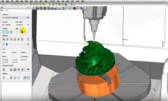
After completing the preliminary path planning, CNC simulation software (e.g., VERICUT, NC Simul) models the tool paths and verifies whether there are problems such as interference, overcutting, or vibration. Through a number of rounds of simulation and path optimization, the engagement angle, cutting depth, and toolpath are adjusted to ensure ultimate machining accuracy and stability.
Typical Case: Programming Practice for Titanium Alloy Spiral Impeller
The titanium alloy spiral impeller of an aero-engine is with machining diameter of Φ180mm, blade thickness less than 2mm, and large curvature change. The NX CAM system was used for programming, along with five-axis equidistant machining strategy and dynamic tool axis obstacle avoidance function. The end machining performance was:
- Machining cycle shortened by approximately 35%;
- Surface roughness controlled within Ra 0.3μm;
- No interference or overcutting;
- Tool life increased by approximately 1.8 times.
This case shows that with reasonable modeling, path control, segmentation strategy, and simulation optimization, high-quality CNC programming for spiral surface impellers is fully achievable.
Conclusion
CNC programming of spiral surface impellers presents several technical challenges, including poor path continuity, tool interference, and posture complexity control. However, with high quality modeling, five-axis equidistant path methods, intelligent tool pose control, and precise simulation optimization, all these difficulties could be addressed very efficiently, significantly improving machining efficiency and impeller surface quality. With continuous advancements in artificial intelligence and path planning, digital twin simulation, and multi-physics machining forecasting technologies, future CNC programming will continue to be smarter and automated, bringing new energy into high-end manufacturing.


