
The widespread application of multistage centrifugal impellers in aerospace compressors, industrial pumps, and gas boosting systems has made their machining technology a significant obstacle in modern production. Especially in complex geometric structures with high accuracy requirements and multistage connection, traditional CNC programming technology is incapable of satisfying the requirements of fine machining. With its capable five-axis linkage control and path planning functions, UG NX as an integrated CAD/CAM/CAE software at a premium level demonstrates obvious application value in machining multistage centrifugal impellers.
Introduction
With continuously improved performance requirements of centrifugal impellers in recent fluid machinery, traditional CNC programming methods cannot meet precision machining requirements of multistage centrifugal impellers any more. Especially for multistage structure and complicated flow channel transition linkage machining, the traditional three-axis programming is generally powerless to achieve precise toolpath control and ensure machining accuracy. As a robust integrated design and manufacturing platform, UG NX has rich five-axis path planning capabilities to address the problem effectively. This paper introduces the application of UG NX software in multistage centrifugal impeller path planning, expounds its main technical modules, and demonstrates practical application effects by examples.
Structural Characteristics and Machining Challenges of Multistage Centrifugal Impellers
Multistage centrifugal impellers consist of a number of impeller stages in series, and within each stage there are numerous blades, hubs, and flow channels. Their main features are as follows:
Complex Free-Form Surface Structure
Generally used in power machinery such as gas turbines, aero-engines, and high-speed compressors, multistage centrifugal impellers consist of a series of series-connected impeller stages with a number of blades, hubs, and flow channels in each stage. The most striking structural feature is that the blades are 3D free-form surfaces with deep spatial twist and diverse curvature variations when extended out from the hub. Blade sections are non-linear and non-uniformly varied, and the whole geometry is extremely complex, greatly increasing the complexity of CAD modeling and CAM path planning. Traditional three-axis machining often cannot achieve full tool engagement, prone to machining blind holes and local error accumulation.
Interference and Accessibility Challenges Caused by Multistage Structures
Multistage impeller components are closely spaced, especially in the interstage connection areas and inner cavity blade roots, where room is minimal, with considerable tool-interference danger on tool entrance and tooling. Inadequate path planning easily leads to tool-front-stage blade or rear-stage hub impacts. Coupled with inadequate spacing between blades, the rigidity and vibration dangers of long tools also increase. Therefore, multistage structures impose not only higher requirements on path planning methods but also on tool length, stiffness, and obstacle avoidance capability.
Extremely High Precision and Surface Quality Requirements
As central elements of kinetic energy conversion, multistage centrifugal impellers impose extremely rigorous precision and surface quality requirements during production. At high-speed operations, even the slightest topographic error or surface imperfection can result in flow perturbation, loss of efficiency, or even fatigue failure. Typically, blade geometric tolerances need to be kept at ±0.02mm, and blade surface roughness (Ra) should be less than 0.4μm to ensure favorable aerodynamic performance and wear resistance. Such accuracy is much higher than standard component machining, requiring more stringent demands of the path precision and machining stability of CNC programming.
Five-Axis Linkage Machining as a Necessity
Due to the dual limitations of complex surface and dense structure, traditional three-axis milling finds it difficult (compete) the manufactory task of multistage centrifugal impellers. Five-axis linkage milling ensures continuous cutting and high-efficiency material removal of complex surfaces by modifying the tool’s spatial posture in a flexible manner, opening up the possibility of high-precision machining. Especially for blade tips, root surfaces, and interstage connection pieces, five-axis linkage can avoid path jumps and posture sudden changes, acquiring smooth, efficient, and interference-free machining paths. Therefore, five-axis programming technology becomes the most important support for machining multistage centrifugal impellers.
Advantages of UG NX in Multistage Impeller Programming
Faced with the complex geometry of multistage centrifugal impellers, full CAD modeling, CAM path generation, and five-axis simulation functions in the UG NX software are highly applicable to similar multi-axis high-precision application scenarios. Under the environment of NX, C2 continuous surface modeling, auto path obstacle avoidance, equidistant finishing strategy, and tool posture control can be realized, significantly improving path stability and machining precision. Meanwhile, NX offers good compatibility with popular high-end machine tool systems (e.g., MAKINO, DMG MORI, etc.), offering high-performance post-processing output and creating an efficient closed loop from modeling, path planning to machining execution, meeting the technical demands of multistage impeller complex manufacturing processes.
Key Technical Modules of UG NX in Path Planning
UG NX path planning capability includes a number of modules and methods. Here is an application analysis of a number of main technical modules:
Multi-Axis Path Module (Fixed and Variable Axis Contour)
UG NX offers five-axis contour milling with fixed or variable axis path choices depending on blade shape variation. With leading curves and machining boundaries defined, the tool axial angle may be precisely controlled, reducing sudden changes in paths and posture interference effectively. This smoothes out free-form surface blade machining with continuity of paths while machining.
Flow Channel Machining Strategy (Blade Area Machining)
Blade Area Machining ability in UG NX is particularly suited for the flow channel parts of multistage centrifugal impellers. It enables automated identification of the boundaries of blade parameters for easy composite application of various types of paths, including contour lines, streamlines, and Z-level paths. During machining, the tool axis direction can be changed in a flexible way so that the tool can track complex surface changes, and self-test interference and avoidance can be implemented to ensure path continuity and security during machining.
Multistage Structure Management and Group Path Control
For the complex multistage centrifugal impeller structure, UG NX offers a group path control function, using which the machining sequence of groups of multiple impeller stages can be scheduled automatically and the stage-stage relationship optimized by group path scheduling. This function can effectively reduce the complexity of tool posture resetting in machining to zero, eliminating the risk of repetitive position errors and path breaking.
Typical Path Planning Process and Application Cases
Taking a particular multistage centrifugal booster pump impeller as an example, this paper shows the overall process of UG NX path planning:
- CAD Modeling and Structural Grouping: Import the 3D model of the multistage centrifugal impeller, perform geometric identification on the impeller structure of each stage, and assign appropriate surface areas for definition.
- Blank Modeling and Tool Library Setting: Generate a blank model based on the impeller structure and establish a tool database matched with machine tool parameters to ensure the accuracy of tool selection.
- Roughing Path Planning: Employ the Z-level Roughing approach to have the outer ring blank machined as soon as possible such that the blank shape has already satisfied initial requirements.
- Blade Surface Machining: Employ the Blade Area Machining module to machine the blades of every stage, producing equidistant streamline five-axis paths for the uniform machining of every stage’s blade surface.
- Channel and Transition Surface Treatment: Machine the hub-to-blade root junction area by employing the Morph Between Surfaces strategy to maintain tool posture continuity.
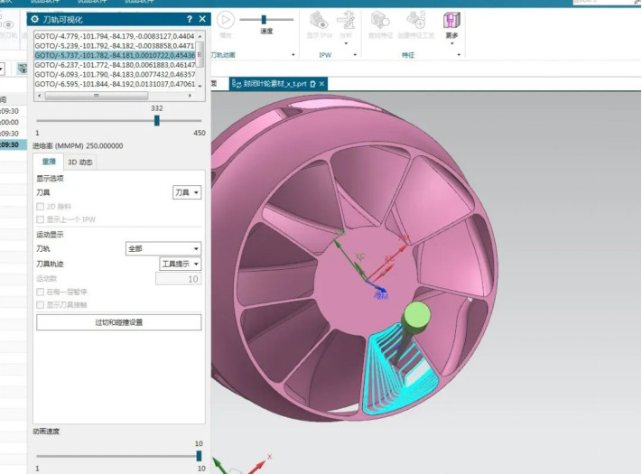
- Simulation and Interference Checking: Use the simulation module of UG NX to conduct full-process interference checking to ensure no interference or over-limit issues during machining.
- Post-Processing and Machine Simulation: Generate NC codes suitable for specific machine tool control systems and preview the entire path through a virtual machine tool model.
Path Quality Analysis and Machining Effects
Practical experience in machining shows that path generated by UG NX software is obviously superior to traditional path schemes. The following comparison information are listed:
| Evaluation Item | Traditional Path Strategy | UG NX Advanced Path |
| Programming Time | Over 18 hours | Approximately 9 hours |
| Number of Tool Posture Abrupt Changes | Frequent (>30 times) | Smooth (<10 times) |
| Surface Roughness | Ra 0.6–0.8μm | Ra 0.35–0.4μm |
| Machining Interference Risk | High, requiring manual correction | Full-process automatic avoidance |
| Stability | Slight vibration marks | Stable cutting |
These data show that the machining quality and efficiency of multistage centrifugal impellers can be substantially enhanced by using UG NX’s optimized path planning, lowering the cost of manual repair and trial cutting and improving machining stability.
Conclusion
Application of UG NX for CNC machining of multistage centrifugal impellers demonstrates its big advantage in complex surface processing, path continuity control, and five-axis posture planning optimization. With the expanding software capability and the adoption of new technologies, especially breakthroughs in AI-based path optimization and machine tool digital twin simulation, opportunities for the use of UG NX in high-end fluid machinery production will be broader.


