
As demand for high-performance components in aviation, energy, and high-end automotive manufacturing continues to grow, modeling and programming of machining complex curved components such as impellers has emerged as one of the major challenges in modern manufacturing technology. This paper takes Siemens NX (i.e., UG) as the technical platform, combines 3D modeling and CNC programming processes, and systematically checks out the key steps in impeller modeling, five-axis machining path generation processes, and engineering experience in real cases.
Introduction
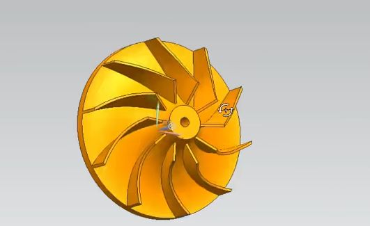
Being a traditional three-dimensional free-form surface structure, the design and manufacturing of an impeller involve complex geometric construction, dynamic balance requirements under high-speed rotation, and cutting behaviors of high-strength materials. Its own fabrication typically has multiple working parts such as hubs, blades, and central shaft holes, with high geometric strength symmetry and extremely high precision demands for manufacturing. As a mature CAD/CAM combined software, UG is frequently applied to modeling and path planning of complex parts, and is most suitable for dealing with such processing workpieces as impellers with severe surface variations and complex machining trajectories.
In modeling and machining a specific turbine impeller made of titanium alloy, I directly benefited in a big way from UG in terms of freedom of modeling, tool path planning flexibility, and simulation-based verification. The efficiency of machining and accuracy of the product are significantly improved with the effective five-axis path generation and 3D modeling capabilities of UG.
Analysis of 3D Modeling Process under UG Platform
Modeling Preparation and Initial Settings
Before modeling, the key mission is to obtain geometric parameters, including outer diameter, number of blades, hub thickness, shaft hole diameter, and blade spatial curvature correctly. These parameters can be recovered from design drawings, physical scanning information, or reverse engineering information. Subsequently, a suitable coordinate system and modeling reference need to be defined. It is recommended to use the Z-axis as the rotation axis to take advantage of the following circular array and five-axis path generation.
Steps for Geometric Feature Construction
Modeling is usually started by developing the hub and main shaft body:
- Base Modeling: Design a base of size 100mm×2mm through the cylinder command.
- Main Shaft Construction: Use the round table tool for modeling, in which sizes are changed to a large round table of 45mm×50mm and a small round table of 20mm×15mm to complete the main structure.
- Shaft Hole and Rounding: Drill a shaft hole of the axis (12mm in diameter) and perform a 20mm fillet processing to eliminate stress concentration.
Next, proceed to the geometric modeling link of the blade:
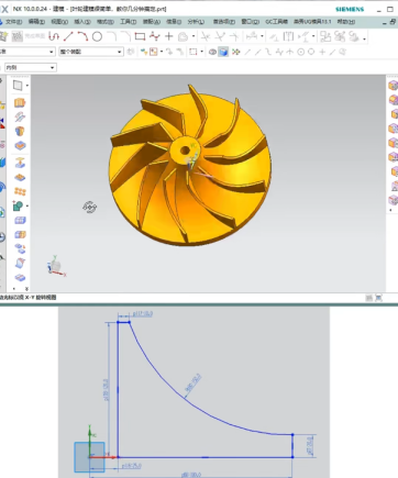
- Blade Sketch Drawing: Select the XZ plane and YZ plane for drawing the spatial curves respectively, and use the spline tool to draw the blade surface bus and the cross-sectional profile.
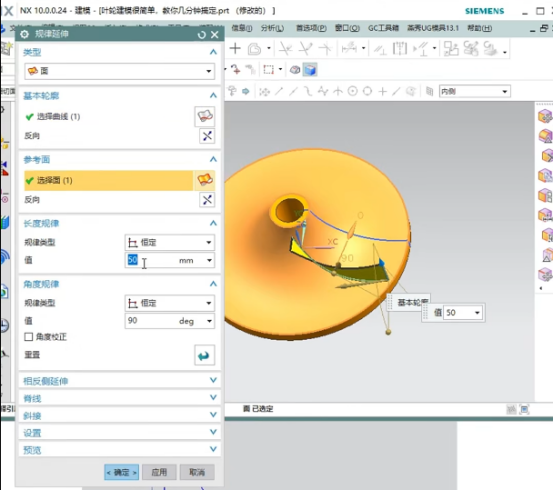
- Blade Molding: Use the “Sweep” command to generate a three-dimensional surface space, and perform a 1mm offset and subsequently extrusion.
- Solid Trimming and Replacement: Use the “Trim Body” and “Replace Face” commands to merge the blade surface with the hub solid.
- Array Replication: According to the given number of blades (e.g., 20 pieces), run a circular array (a piece for a 18°) to build a complete impeller structure.
Model Optimization and Detail Processing
After modeling, the model needs to be detailed:
- Round the transition surfaces of the leading edge and blade root with 5mm, 3mm, and 2mm radii respectively using the “Edge Blend” tool for strength and machining finish of the blade;
- Use the “Surface Check” function to identify potential modeling errors and prevent calculation halts during path generation;
- The rendering module is used to show the final effect beforehand in order to eliminate visual and process conflicts in advance.
Programming Path Generation Strategies in UG
Machining Area Division and Strategy Matching
Depending on the differentiated characteristics of the impeller structure, corresponding machining schemes need to be adopted:
- Hub and Main Shaft Area: 2.5-axis or three-axis finish milling should be performed with simple and controllable paths
- Flow Channel between Blades: Five-axis “streamline cutting” is proposed, which has the capability of aligning the tool with the surface normal for improving surface quality;
- Blade Tip Area: Use “contour finish milling” or “Z-level machining” strategies to preserve tip precision.
Tool Path Generation and Tool Axis Control
UG’s CAM module provides various path generation methods:
- Common modules such as “Flowline Machining”, “Fixed Axis Projection”, and “Five-Axis Equidistant” can achieve efficient continuous paths;
- Use the “Tool Axis Vector Control” function to dynamically adjust the tool posture to avoid interference and undercutting;
- Use slow advancing and retreating motions at the tool entry and exit, especially at the inlet blade position, to avoid edge chipping and vibration.
Recommendations for Machining Parameter Settings
The following are general parameter recommendations (finely tunable according to special materials and equipment):
| Parameter Category | Recommended Value |
| Spindle Speed | 12000~18000 rpm |
| Feed per Tooth | 0.02~0.08 mm/tooth |
| Cutting Depth | 0.2~1 mm |
| Stepover | 0.1~0.4 mm |
| Tool Type | Ball end mill, taper shank tool, slotting tool |
Case Study: Modeling and Machining of Ti-6Al-4V Titanium Alloy Impeller
In a modeling task for a titanium alloy impeller, we used the following procedure:
- Modeling Cycle: The whole modeling took approximately 3 hours, including the construction of surfaces, guide rail design, array setup, etc.;
- Path Programming Stage: Split management of three phases: roughing, finishing, edge repair;
- Virtual Simulation and Optimization: The UG simulation module achieved tool path verification within an error margin of ±0.01 mm, and rearrangement of paths reduced tool change times by approximately 15%;
- Machining Preview: (Link) with a virtual machine tool through the post-processor to preview the whole machining process and ensure the safety and realizability of the path logic.
Common Problems and Solutions
| Problem Type | Cause Analysis | Solution Recommendations |
| Tool Interference | Unreasonable tool axis posture control | Enable interference detection and optimize tool vector control strategies |
| Surface Modeling Failure | Gaps in surface stitching | Use “Patch Surface” or reconstruct the intersecting area |
| Discontinuous Path | Abrupt guide rail curvature or excessive control points | Simplify control points and insert smooth transition segments |
Conclusion
From this study of UG’s usage in impeller 3D modeling and programming practice, it is shown that this platform has very high flexibility and smart advantages in processing intricate free-form surface parts. From modeling and path design to machining simulation, UG can realize highly integrated one-stop operations, which significantly enhances manufacturing efficiency and part quality.


