
As the impeller is the most important component of many fluid machinery (such as aero-engines, turbines, and compressors), the accuracy of the shape of the impeller directly affects the aerodynamic performance, mechanical efficiency, and operational stability of the machine. Impellers have extremely complex geometric structures and extremely high demands for precision manufacturing. As a result, traditional detection methods (such as projectors and calipers) are incapable of meeting precision manufacturing demands.
In this work, a method of impeller shape deviation control using a Coordinate Measuring Machine (CMM) is proposed, which covers reference point establishment, 3D scanning approaches, error fitting test, deviation feed-back, and manufacturing adjustment. By establishing a closed-loop control system of detection-analysis-feedback-correction, a smooth process from design model to real-time control at the production line is achieved, providing full support for high-accuracy impeller machining. Coupled with the processing technology of a typical aero-engine titanium alloy impeller, the excellent performance of this program in improving pass rate, shortening trial production time, and reducing rework cost is verified.
Introduction
Over the past few years, precision requirements for producing an impeller in aviation, energy, and chemical sectors continued to increase. Especially in the case of high-complexity processes such as five-axis (linkage) machining and integral impeller additive manufacturing, precise control of impeller morphology post-processing is currently the quality management focus link. Due to its advantages of high accuracy, flexibility, traceability, and high automation, the Coordinate Measuring Machine (CMM) has become the major instrument for the detection and control of impeller shape error. In actual production, without precise detection and feedback control systems, problems such as profile errors, centricity deviation, tilt distortion, and blade pitch-thickness uniformity will directly affect aerodynamic performance and even result in overall machine instability. The scheme presented here is presented on this foundation, in which full-process closed-loop quality control of impellers from design to production is the target.
Types of Impeller Shape Deviations and Detection Challenges
Since impellers are high-precision rotating components, the form of impellers has a close relation to the balance, aerodynamic performance, and fatigue life of equipment operation. The form errors affecting performance under real manufacturing conditions are mainly the following types:
- Profile Error: Identifies the infinitesimal difference between the design 3D model and the actual profile of the blade surface, typically manifested in the form of surface discontinuity, arch deviation, excessive rounding of sharp edges, etc. Such errors are likely to occur in regions of intricacy in curvature and straightaway reflect the surface processing capability.
- Concentricity Deviation: i.e., how much the center hole axis of the impeller deviates from the center on which the blades are mounted. If not well controlled, it will produce uneven centrifugal force at high speed running, leading to unstable operation or even early failure.
- Tilt and Bending Errors: Most likely to occur in thin-walled parts or in transition zones, such as the blade root, resulting in deformation of posture due to clamping, cutting forces, or thermal stress, ultimately affecting assembly fit and dynamic balance.
- Inconsistent Blade Pitch and Thickness: In multi-blades, if the angle distribution of every blade is unsymmetry or the difference in thickness is large, the symmetry of the entire will be destroyed, creating local flow separation and unsymmetric vibration, significantly reducing aerodynamic performance.
The majority of the deviations contain complicated spatial patterns, especially for free-form surface and deep cavity impellers, which are more (deep-rooted) and less able to be accurately measured by traditional contact measurement or 2D projection methods. Moreover, impellers are often made of high-reflection and compound processing materials such as titanium alloys and superalloys. When non-contact optical measurement or probe-type profilometers are employed, they are prone to disturbance by reflection of the surface, blurring of edges, or soft deformation and therefore lead to erroneous information.
Therefore, the introduction of a Coordinate Measuring Machine (CMM) capable of high-precision spatial modeling and flexibility to complex 3D geometry has emerged as the first choice to tackle such detection challenges. It not only provides micron-level spatial point cloud data but also possesses the capability to perform automatic edge finding, multiple measurement, and direct comparison with CAD models, thereby achieving (full-domain blind area-free) geometric deviation measurement of impellers. In advanced quality control and manufacturing applications, the value of the CMM system is no longer a measuring device but a built-in link to deliver geometric precision and closed-loop manufacturing.
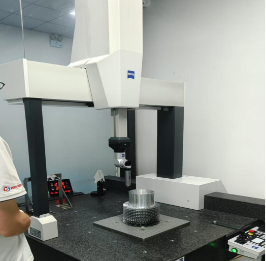
Review of Technical Principles of Coordinate Measuring Machines
The CMM includes machine base, probe (photoelectric laser or touch type), probe holder, worktable, and measurement and control system. Its XYZ three-axis motion system provides micron-level position accuracy (e.g., air-float guide use), up to 0.1 μm probe resolution, and point contact or non-contact scanning feature. Point clouds or curve profiles of the part are formed by aligning the probe, sampling motion, and collecting coordinates. In shape control of impeller, the key is to accurately obtain the discrete coordinates of the surface of the blade, establishing a high-quality data foundation for error analysis.
Design of Deviation Control Scheme Based on CMM
In precision manufacturing of impeller, how to realize efficient geometric deviation control from high-precision measurement data is the key to guaranteeing product consistency and performance reliability. The Coordinate Measuring Machine (CMM) is not only spatial perception and high-resolution, but can also deeply penetrate CAD/CAM processes in order to achieve a manufacturing close loop of detection, analysis, and correction. The below is a sequence of CMM-based deviation control schemes delineated and applied in practice projects:
Establishment of Digital Detection Reference System
I believe the key to measurement precision begins with the correct setup of the detection reference system. In the very early stage of the scheme’s deployment, we used the CAD model to import it into the CMM system to build a uniform part measurement coordinate system, determine the X/Y/Z directions of the axis, and take significant geometric feature surfaces such as the impeller center hole, blade inlet line, and outlet rim as spatial reference elements. This approach not only provides a stable coordinate basis for future multi-batch impeller detection but also establishes a good foundation for multi-station switching and automatic comparison analysis, minimizing human interference.
Multi-Section 3D Scanning Strategy
In light of the observation that impeller shapes are largely complex free-form surfaces with close blade spacing, the design uses composite probes or laser scanning heads to perform divided scanning of functional regions such as blade channels, blade root transition areas, and rim end faces. To ensure spatial resolution and data density, we also establish an automatic probe exchange system using contact probes and non-contact scanning probes of different sizes and shapes to collect high-density point cloud data point by point. With this method, not only are the measurement blind areas successfully removed, but measurement efficiency and surface fitting quality are also improved, especially applicable to high-difficulty positions such as blade corners and grooves of the flow channel.
Error Fitting Analysis and Visual Feedback
After getting the high-precision point cloud data, after the application of professional analysis software (e.g., PC-DMIS, Calypso), we perform spatial fitting between the measurement point cloud and CAD theoretical model, give output error thermal maps and vector offset maps, and visually show error distribution trend and dense regions. For example, in a high-pressure turbine impeller project, this function was applied to easily determine systematic thickening at the tip of the intake part’s blade. In addition, a cross-sectional profile surface is obtained based on a cubic B-spline fitting approach, aligning the theoretical and measured profiles to compute the error di,j at each sampling point, and obtaining the maximum error δi of each cross-section and the maximum deviation of the overall profile in order to decide whether the part is out of tolerance range and assess processing stability.
Process Closed-Loop Feedback Correction
My experience illustrates that data from measurement analysis can be utilized only to the full extent in use during playing out their value when fed back into the processing system. For our system, significant deviation information produced by the CMM is fed back online to the CAM programming terminal to optimize locally tool paths, five-axis linkage positions, and feed rates, or assist in readjusting clamping methods and positioning references, in order to achieve instant correction control based on detection findings. For example, in a titanium alloy impeller finishing case, by bringing the too much residue data back to the middle of the flow channel, the tool lifting path was corrected successfully, the loop overcutting problem was eliminated, and the surface flatness and geometric accuracy improved sharply.
Using the above four modules in conjunction, the CMM is not only a precise detection platform, but also becomes a key link in product design, production, and inspection of bonding. Its integration and intelligence experienced throughout the entire process of precision impeller machining are more and more driving the transformation from “post-event detection” to “process control,” providing good technical support for high-quality manufacturing of complex components.
Summary
This work systematically proposes a sequence of CMM-based impeller shape deviation control strategies. On the basis of digital measuring reference, local scanning, multi-dimentional error analysis, and correction on manufacturing feedback, closed-loop quality control process from detection to manufacturing is established, and significant improvements in processing accuracy and consistency of the impeller are achieved. I believe that with the development of intelligent manufacturing and artificial intelligence technologies, the scheme will further integrate real-time error prediction models and unmanned measurement systems in the future, reaching “unmanned measurement + intelligent process control,” driving the impeller manufacturing to a new age of digitization and intelligence.


