
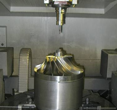
Since high-performance integral impellers are used extensively in aero-engines, compressors, and equipment for energy, etc., their machining processes incline toward integration, high precision, and complexity.
Complex curved surface impellers generally have deep and narrow flow channels, large torsion angles, changeable root fillets, and non-developable free-form surfaces, which make traditional three-axis or four-axis programming difficult to handle interference avoidance, posture control, and trajectory optimization. Through different project practices, I have deeply realized that relying solely on experience in programming is not anymore capable of meeting the requirements of modern impeller machining in terms of quality consistency and controllability of the process. It is against this backdrop that tool path simulation software emerged. Especially in five-axis linkage conditions, the simulation system not only acts as a programming verification tool but also as a necessary guarantee of secure, efficient, and precise machining.
Programming Difficulties of Complex Curved Surface Impellers
Not only is path planning of complex curved surface impellers challenging, but also the creation of efficient, stable, and interference-free five-axis tool trajectories in thin structures with confined space and drastic changes in curvatures. Firstly, the minimum blade spacing is typically very close, and the flow paths tend to twist and spiral, making the tool highly susceptible to interference, primarily spatial conflicts between fixture and the shank of the tool. In addition, five-axis posture control is particularly difficult in deep cavity areas. When this sudden axial change occurs, not just will the machining path cause sudden breakpoints, but it can even lead to impact or overcutting during actual machining.
In actual use of UG to program and model, I attempted automatically generating finishing paths but, with issues such as abrupt changes of curvature and insufficient surface smoothness in the original model, the tool paths continued to warn against interference during simulations, and even some tool trajectories remained uncoherent and non-smooth. All these problems not only increase the workload of (post-stage) debugging for the program but also raise the risk of workpiece scrapping by a large margin. Therefore, I have come to believe that modeling precision and simulation tools have an intimate technical relationship. Only with reliance on good-quality 3D models and (supplemented with) exact simulation detection can stable and credible five-axis linkage machining paths be established.
Core Functions and Integration Value of Simulation Software
In programming machining of complex curved surface impellers, empirical judgment is usually employed in conventional path programming methods, and it is difficult to immediately discover machining defects with inappropriate path design, abrupt posture change, or interference. Being an essential instrument in the current computer numerical control programming process, machining simulation software not only provides visual and interactive previews of the machining process but also makes comprehensive improvements on the precision of machining, process safety, and tool utilization by intense integration with CAD/CAM systems. With dynamic simulation analysis capabilities and high-precision modeling functions, programmers can conduct closed-loop verification from process parameter optimization to tool path verification within a virtual environment with minimized trial cutting cost and rework risk. The paper further explores the simulation software’s main functions and integration value in complex curved surface impeller programming from four aspects.
3D Tool Path Dynamic Visualization
Simulation software such as VERICUT, NX CAM, and PowerMill provide richly restored dynamic views of milling, which can panaramically display the movement relationships among machine tool, tool, workpiece, and fixtures, enabling operators to foresee the rationality of the path and intuitively identify potential points of risk at the programming phase. For example, in a holistic rotor 17-blade machining assignment, I have picked up from simulation that the tool feed path had cutting jitter on the area of the 12th blade, which was rectified after posture and trajectory parameters’ optimization.
Interference Detection and Posture Optimization Analysis
The interference detection function can real-time judge spatial conflicts between the tool, fixtures and workpiece, equipment and tool, and detect smoothness of five-axis posture change and warn about limit angle. In areas where blades have complicated curvature, abrupt posture change is likely to induce serious effects such as unstable cutting and part scrapping. Through posture smoothing and limiting control, the simulation software can offer significant aid to five-axis trajectories’ stability design.
Material Removal Simulation and Residual Material Tracking
Residual material control is essential for the improvement of surface integrity and efficiency in impeller rough and finish machining. The simulation platform can present the dynamic material removal and unprocessed areas accurately, and through that, further machining path planning for the bottom of the flow channels and small-angle areas is permitted. For example, when applying PowerMill and VERICUT in combination, I included additional machining paths for the remaining material problem at the impeller root with small-diameter ball tool, which improved the surface quality significantly.
Dynamic Machining Parameter Adjustment and Feedback
Some of the high-order simulation software can dynamically respond to mimic the machining physical process, mimicking significant influential parameters such as spindle load fluctuations, tool wear modes, and workpiece thermal deformation, to facilitate real-time simulation optimization of the cutting process. With analysis of the load data during the simulation, the system automatically adjusts the feed rate and spindle speed to achieve adaptive optimization of machining parameters. During a machining process for an impeller of a titanium alloy, I used this function to simulate tool thermal deformation and load regulation. Under dynamic compensation of feed rate and adjustment of cutting depth, not only tool life was extended by approximately 20%, but also the surface burning caused by high temperature was significantly restrained, and there were excellent quality machining products. Such feedback control of parameters is particularly significant in the machining of high-value products and forms an essential part of the realization of intelligent manufacturing.
Integration Practice of Modeling and Programming
3D Modeling Process
3D modeling of intricate impellers has a tendency towards combining theoretical design with reverse engineering. Using UG’s free-form surface function module, discrete DAT points are loaded, and spline fitting with smooth and continuous curves are created using smoothing processing for the instant break of curvature and cusps. Especially for areas of instant break of the leading edge fillet radius, we rework the transition of curvature by means of bridge and tangent constraint measures so that the model may be made machinable.
Based on this assumption, transformation replication is utilized to achieve even placement of several blades, and Boolean operations are utilized to generate a complete solid. The key to success in this operation is to have even posture between every blade to avoid coordinate mistakes or incoherent paths for future path generation.
Machining Process and Tool Path Design
The machining path is derived from the model’s structural parameters and tool selection. In general, ball tools of large diameters are utilized in rough machining for increasing material removal rate, and then small tools are utilized in finish machining of the fine structural regions. During path programming, I pay particular attention to tool entry posture and retraction direction, and utilize UG and PowerMill to control simultaneously the curvature change of tool entry path in a manner to avoid side edge chipping of the tool in zones with large torsion angles.
Whereas at the same time, while verifying the path, there is a need to make maximum use of the simulation platform for full-path interference simulation and spindle angle change detection so that the stability and security of the code generated when run on actual equipment would be ensured.
Functions of Tool Path Simulation Software
Tool path simulation software (e.g., VERICUT, NX CAM, Mastercam Simulation, CGTech, ModuleWorks, etc.) serves the following functions at the programming stage:
| Function | Description |
| Tool Path Visualization | Simulates how the tool moves, enters/retreats, and follows the cutting sequence in a 3D environment, enabling programmers to intuitively verify the rationality of the tool path and adjust it in a virtual space. |
| Interference Checking | Detects whether the tool collides with the workpiece, fixtures, or machine tool. This function identifies spatial conflicts (e.g., tool shank interference with fixtures or tool edges scratching the workpiece) to prevent equipment damage or workpiece scrapping during actual machining. |
| Overcut/Undercut Detection | Judges whether certain areas are over-machined (overcut) or under-machined (undercut), which directly affects the precision of the finished product. For complex curved surfaces (e.g., impellers), this function ensures that the tool path strictly matches the design model without dimensional deviations. |
| Surface Quality Prediction | Analyzes the impact of tool path strategies (e.g., feed rate, tool type, cutting depth) on the surface finish (e.g., Ra value) of impellers. It helps optimize parameters to achieve the required surface roughness and avoid defects such as scratches or vibration marks. |
| Time and Efficiency Optimization | Optimizes the tool path to reduce idle movement time (e.g., unnecessary tool retraction or long-distance displacement) and shortens the overall machining cycle. This function improves production efficiency by minimizing non-cutting time while ensuring processing quality. |
| Digital Twin Simulation | Aligns the virtual machining environment with actual equipment parameters (e.g., spindle speed, axis movement limits, tool specifications), enabling “true-to-reality” simulation. This ensures that the programmed tool path can be directly applied to physical machines, reducing trial cutting costs and debugging time. |
Conclusion
Precise machining of intricate curved surface impellers is increasingly dependent on solid simulation platform support. By using simulation software in realizing organic integration of modeling optimization, path design, dynamic simulation, and parameter verification, it is possible to really prevent uncontrollable risks in general programming methods and improve programming efficiency, quality consistency, and production stability. As a front-runner CAM programming and machining engineer, I deeply realize that the value of tool path simulation is infinitely greater than “looking”; it is an essential tool related to design accuracy, production safety, and product competitiveness. In the future, with the constantly accelerating development of intelligent simulation technology, its position in producing complex curved surface impellers will become increasingly important, constructing more robust digital wings for China’s high-end manufacturing.


