
In accordance with growing demands for micro-sized, high-performance impeller structures in the aerospace, medical device, and high-grade energy equipment industries, standard machining tools and techniques have proved unable to meet high-precision manufacturing requirements for micro-complex structures. Micro tools as high-precision cutting tools with diameters of φ0.1–2.0 mm are becoming main tools for precision impeller machining in greater numbers.
Introduction
Because they are the most important constituents of kinetic energy conversion, micro impellers typically possess complex small size, thin-wall, and multi-curvature structures in aero-engines, micro-pumps, and gas turbines. The machining precision has direct relation to the machine’s overall performance and service life. In micro-structure machining with conventional-sized tools, deviations in machining precision or even workpiece damage is the norm with oversized tool size, insufficient rigidity, or inadmissible cutting paths. Micro tools demonstrate inestimable value in impeller micro-machining due to their very small edge diameter and ability to adapt at high speeds.
But micro tools are also faced with a series of application challenges, including easy breakage caused by low rigidity, temperature-accelerated wear, and unstable micro-cutting force control. Therefore, systematic study is urgently needed from multiple aspects such as tool structure design, material performance, machining strategies, and intelligent equipment coordination.
Structural Characteristics and Material Systems of Micro Tools
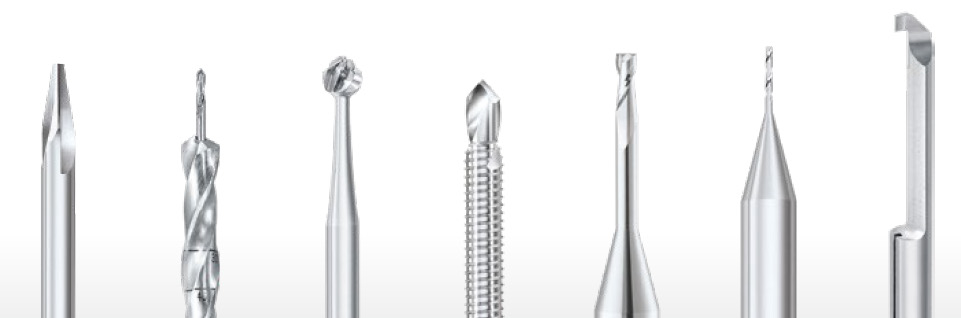
The geometric configuration of micro tools determines the machining quality and stability of micro tools, when machining impellers. The common edge diameter of common micro-mills ranges from 0.1 to 2 mm, and some ultra-micro tools are less than 0.05 mm. In accordance with high-speed spindles, their shank diameters are mostly using industry standard specifications of φ4 mm or φ6 mm to enhance clamping stability. The relief angle and helix angle are controlled within 15°–30° to ensure synchronization of cutting force and chip removal, and to effectively prevent thermal tool deformation. Edge length is designed to be controlled within the minimum range, via a standard overhang ratio of less than 4:1, thereby promoting rigidity and reducing runout.
For tool material, ultra-fine grain cemented carbide is presently the trend in matching thermal stability and high hardness. For cutting high-temperature materials such as nickel-based alloys and titanium alloys, coated cemented carbides (e.g., AlTiN, TiSiN) exhibit adequate oxidation resistance along with thermal protection characteristics. When cutting polycrystalline composite and non-metal impellers, polycrystalline diamond (PCD) achieves excellent balance of surface quality and service life due to its extremely high edge sharpness and wear resistance.
Key Challenges in Machining
In high-precision machining of a superalloy impeller or micro-complex structure, the tool and process system are confronted by a series of issues in the micro tool and multi-axis machining state. The following is the systematic description of the main machining issues:
Insufficient Tool Rigidity and Fracture Risk
Due to their very tiny size of structure, micro tools have little inherent stiffness and are very prone to deflection, vibration, or even breakage under high-speed, long-overhang, or improper clamping conditions. As the tool sees through the roughing operation, due to extreme fluctuation in cutting force, the point impact further amplifies the structural weaknesses of the tool, leading to edge chipping or the complete fracture of the tool. In addition, thin-walled work or complex flow channels may induce lateral forces on the tool due to workpiece elastic deformation, thereby exacerbating instability risk.
High-Speed Wear and Heat Accumulation Effect
While machining high-strength heat-resistant alloys, substantial cutting heat is generated between chips and the tool rake face with focal heat in the narrow edge region, leading to rapid degradation of coating and tool face wear. The heating buildup can also cause thermal cracks, adhesive wear, and built-up edge effects, significantly impairing machined surface integrity and dimensional tolerances. Thermo-mechanical coupling effects of these kinds drastically reduce tool life with control by effective cooling and materials of high thermal stability.
Difficulty in Controlling Micro-Cutting Forces
During the machining of complex surfaces or small-radius geometries, though cutting force is minute, its minor variation tends to lead to local machining anomalies. For example, a small deviation in feed direction would create micro-burrs, edge chipping or surface cracks. Although such defects are not initial large ones but could harm the accuracy of the aerodynamic profile, thereby triggering premature fatigue crack growth or performance degradation of the impeller. Also, insufficient control would increase non-uniform tool loads, affecting machining stability of subsequent operations.
Process Optimization and Application Strategies
In order to effectively tackle the poor working conditions of micro tools in machining of superalloy or intricate geometries, process optimization needs to be addressed from different fronts such as tool paths, cutting parameters, and tool surface engineering. The following approaches have proved significant success in high-precision manufacturing practices.
Tool Path Optimization
Reckoned path planning is the primary necessity to improve the stability of micro-machining. The continuous engagement toolpath is able to damp local cutting force distortions and minimize the likelihood of thermo-mechanical shock. The combination of small step pitch (less than 10% of the tool radius) and high-frequency feed strategies (low feed rate at higher spindle speeds) can significantly improve surface uniformity and structural soundness of the machining zone. Apart from that, reasonably compressing the length of air cutting path contributes not only to reducing the expansion of heat-affected zone but also to reducing ineffective tool wear at no-load conditions.
Fine Parameter Control
The range of micro tool parameters is extremely narrow and requires fine control methods to be applied. Typical process parameters are as follows:
- Spindle speed: 30,000–100,000 rpm;
- Feed per tooth (fz): 1–3 μm/tooth;
- Cutting depth (ap): 0.01–0.03 mm.
- High feed rates in conjunction with high speed are capable of successfully restraining the cutting load peak and avoiding edge chipping and concentration of stress issues. Concurrently, high-pressure cooling (≥7 MPa) or minimum quantity lubrication (MQL) is recommended for improving chip evacuation efficiency and restraining local overheating and tool adhesive wear.
Coating Technology Innovation
Tool surface coatings are of utmost significance in the promotion of the wear resistance, thermal shock resistance, and prevention of built-up edges. Multilayer nano-composite coatings such as AlCrN and AlTiN exhibit high thermal hardness and oxidation stability, suitable for high-precision micro-milling of superalloys and titanium alloys. In cutting low-hardness materials such as aluminum alloys and magnesium alloys, DLC (diamond-like carbon) and CrN coatings can effectively hinder adhesive wear through their excellent anti-friction character and chemical stability.
Over the past couple of years, technological advancements in functionally graded coatings technology enabled tools to undertake a number of surface protection functions: the outermost one achieves thermal insulation and oxidation resistance, the intermediate one enhances fracture toughness, and the base one ensures maximum adhesion, thereby extending overall tool life as well as improving machining stability.
High-End Equipment Boosting Micro Tool Manufacturing
Take WALTER’s HELITRONIC MICRO five-axis high-precision grinder, for example. The grinder is purpose-designed for tool diameters φ0.1–12.7 mm and features ultra-high grinding accuracy and repeatability positioning accuracy. Its mineral casting bed has good damping capability, well managing the thermal deformation and structural rigidity. Its five interpolation axes + two positioning axes mode enables one-clamping molding of complicated shapes and can automatically complete tool geometry calibration.
The machine is equipped with on-board 6-axis robot and camera cooling hole positioning, which loads one load in about 9 seconds and greatly improves the efficiency and consistency of micro tool manufacturing. In addition, the CNC control system and automatic compensation strategy improve the symmetry and edge uniformity of multi-edge tools and serve as the platform core to support mass production of precision tools.
Conclusion
Micro tool technology is an important aid in the promotion of high-end precision impeller manufacturing. With precise structural design, advanced material and plating systems, and cooperative application of intelligent equipment, micro tools not only overcome technical bottlenecks difficult to break with traditional machining methods but also provide unprecedented quality and efficiency guarantees for high-end precision impeller products. Prospects in the future, with the continuous evolution of processes and tools, micro tools will demonstrate their respective strengths in more and more extreme applications, making one of the non-negotiable core technologies for precision manufacturing.


